Plasma torch for plasma transferred arc surfacing with two powder feeding systems
O.I. Som
The Paton Welding Journal. - 2023.
- №8. - pp. 73-77.
A new design of the PTA torch (PTA torch) for surfacing of nickel, cobalt and iron-based alloys was developed. It combines two
systems of powder feeding into the arc: the internal and external one. Such a combination expands the technological capabilities
of the PTA torch, and allows surfacing magnetic and nonmagnetic materials. These systems can be used both separately from
each other and together for surfacing composite alloys with separate feeding of the matrix and reinforcing powder material.
In order to increase the efficiency of powder heating at external feeding into the PTA torch, an auxiliary stabilizing gas flow is
used, which allows reducing the powder losses by 10–15 % and improving the deposited bead formation. Optimal flow rates of
stabilizing gas are 4‒5 l/min. The PTA torch effectively operates in the current range of 50‒300 А.
KEYWORDS: plasma transferred arc surfacing, PTA torch design, powder feeding systems, heating efficiency
Introduction
The PTA torch is the main working tool of equipment for plasma transferred arc surfacing. The quality and stability of the surfacing process as a whole depends in many respects on its efficient and reliable operation. In its turn, the efficiency of PTA torch operation is determined by its thermal characteristics and effectiveness of heating and melting of powder in the arc, which greatly depends on the scheme and parameters of its feeding into the arc.
")

Figure 1. Schemes of powder feeding into the arc: а — internal; b — external (1 — electrode; 2 — plasma nozzle; 3 — shielding nozzle; 4 — focusing nozzle; 5 — part)
(Open image in full size: )
At present two schemes of powder feeding into the arc are the most widely used: internal and external [1–3]. In the first case (Figure 1, а), the powder is fed into the arc from inside the PTA torch in the form of a flow of particles uniformly distributed around a circle through a conical slot formed by the plasma and focusing nozzles. In the second case (Figure 1, b), it is fed from outside the PTA torch through one or several openings in the end face of the plasma nozzle. In this case the focusing nozzle is not used.
Mathematical model [1] and experimental studies performed by the author [3, 4] show that the internal scheme of powder feeding is more efficient. It ensures lower powder losses, better formation of the deposited bead, and lower power consumption at the same deposition rate. This scheme, however, has two significant disadvantages. First, at long-term surfacing, particularly of low-melting materials, liquid metal drops can form at the outlet of the focusing nozzle, which leads to violation of the process stability, blocking of powder feed and deterioration of the deposited bead formation.
Secondly, surfacing of ferromagnetic materials with a large quantity of the ferrite phase in their structure is complicated. Under the impact of the magnetic field of the arc, the powder particles hang in the PTA torch distribution chamber, forming a kind of plugs. This is the most noticeable at current above 150 A . This drawback is absent with external scheme of powder feeding. The objective of this work was to combine these two schemes in one PTA torch and to develop such a design of the nozzle part, which would expand its technological capabilities and improve the operation stability.
; 1 — electrode; 2 — plasma nozzle; 3 — shielding nozzle; 4 — focusing nozzle;
5 — part")

Figure 2. Scheme of PTA torch nozzle part with different variants of powder feeding into the arc: а — internal; b — external with stabilizing gas; c — combined (internal + external); 1 — electrode; 2 — plasma nozzle; 3 — shielding nozzle; 4 — focusing nozzle; 5 — part
(Open image in full size: )
Features of the new PTA torch design
Figure 2 shows the schematic of the PTA torch nozzle part, which combines the internal (Figure 2, a) and external (Figure 2, b) schemes of powder feeding. These schemes can be used both separately from one another and together (Figure 2, c; 5, c). The latter variant is highly effective at surfacing composite alloys with separate feed of matrix and reinforcing materials [5]. In this case, two separate powder feeders, operating synchronously, are used, as well as two separate flows of transport gas.

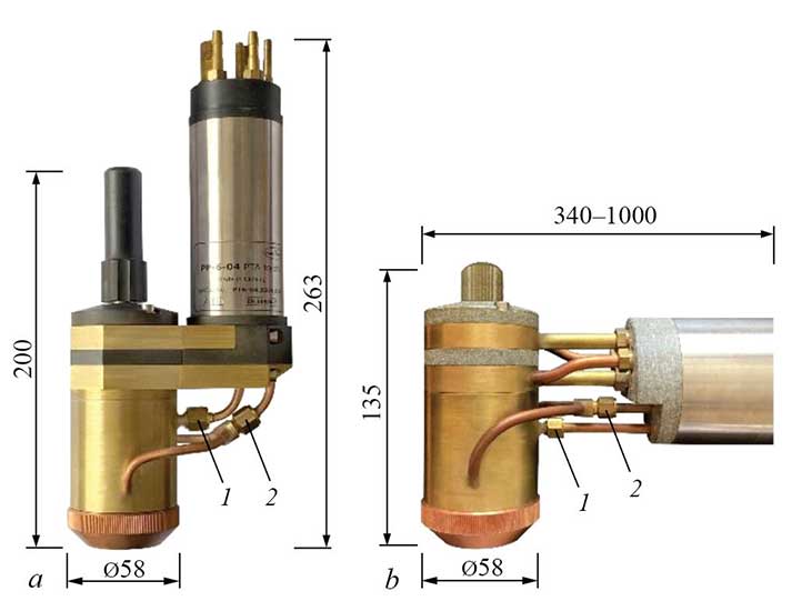
Figure 3. Appearance of PTA torches with two systems of powder feeding: a — vertical type PP-6-04; b — horizontal type PP-6-03M
(Open image in full size: )
This idea was the base for development of two PTA torch variants: vertical (Figure 3, a) and horizontal (Figure 3, b) modifications. They have the same design of the nozzle part. Selection of either variant depends on the design features of surfacing equipment layout. The horizontal variant is more versatile, as it allows surfacing both the internal and external surfaces to different depth.


PTA torches allow surfacing nickel, cobalt and iron-based alloys and composite alloys based on tungsten carbides.
Powder feed variants
Internal powder feed
When the system of internal feeding is used, the powder through inlet nipple 1 (Figure 3, a, b) enters a special distribution chamber, where it is uniformly distributed around a circle by the transport gas and then is blown into the arc through a system of slots uniformly located on the conical surface of the plasma nozzle (Figure 4). The slots promote better cooling of the nozzle and direct the powder particles straight into the most heated central part of the arc. The angle of powder entering the arc is equal to 35° relative to the vertical. The focus of powder particles collision is located at 5 mm distance below the end face of the focusing nozzle (Figure 5, a). This is done so as to eliminate powder particles hitting the focusing nozzle walls and thus to improve the reliability of PTA torch operation.

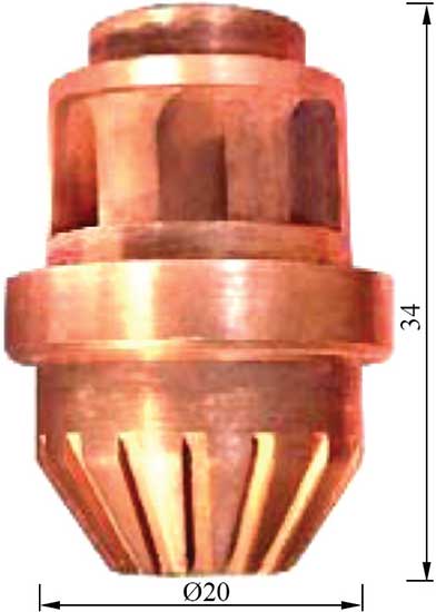
Figure 4. Appearance of plasma nozzle
(Open image in full size: )
For effective heating of powder in the arc, the initial velocity of particles entering the arc should be as small as possible [1]. In this PTA torch, it was possible to bring this parameter to a minimal value, due to original design of the distribution chamber and optimization of transport gas flow rate. For a PTA torch of vertical type, it is equal to 1.5‒2.0 m/s, for horizontal type it is 2.0‒2.5 m/s, that is quite acceptable for heating powder particles of 50‒160 μm diameter, which are widely used for PPS process [6]. To maintain such velocities of powder flowing out, the optimal flow rate of transport gas is 3.5‒4.0 l/min for the vertical variant and 4.5‒5.0 l/min for the horizontal one. Particle movement velocity was determined by photographic method of time-lapse photography [7].
External powder feed
With this scheme the powder together with the transport gas is divided into two uniform flows through a special tee-nipple (Figure 3, a, b), and is then fed into the arc through two openings of 1.4 mm diameter, located on the focusing nozzle end face diametrically opposed to one another. The angle of powder entering the arc is the same as at internal feeding — 35°. The point of powder particle collision is located at 8 mm distance below the focusing nozzle end face (Figure 5, b). The velocity of powder particles flowing out at the PTA torch outlet is noticeably higher than at internal feed both in the vertical and in the horizontal modification, and it is equal to 2.5‒3.0 and 3.0‒3.5 m/s, respectively. This is an essential disadvantage of this scheme of powder feeding into the arc, as increased velocity head of the cold transport gas flow penetrates deeply into the arc column, deforms it (Figure 6, b) and lowers the plasma temperature in the heating zone. Arc deformation leads to deterioration of powder heating, and, consequently, to increase of its losses and worse formation of the deposited bead.
, external (b) and combined (c) powder feeding
schemes")
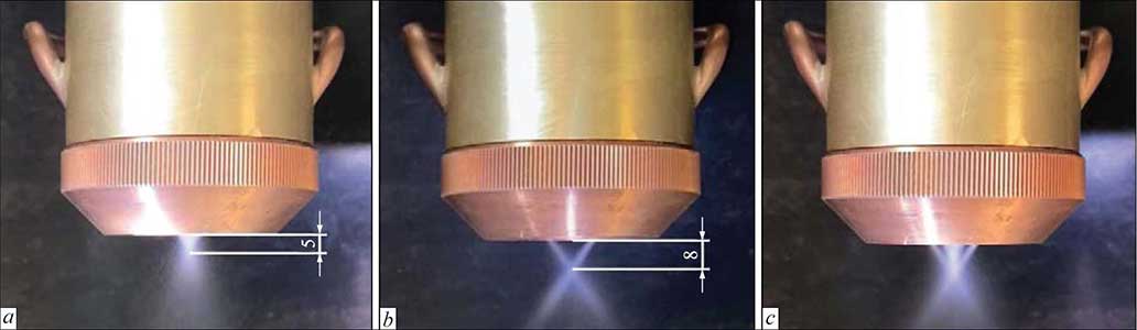
Figure 5. Appearance of plumes of powder flowing out of the PTA torch with internal (a), external (b) and combined (c) powder feeding schemes
(Open image in full size: )
, external (b) and combined (c) schemes of powder feed")
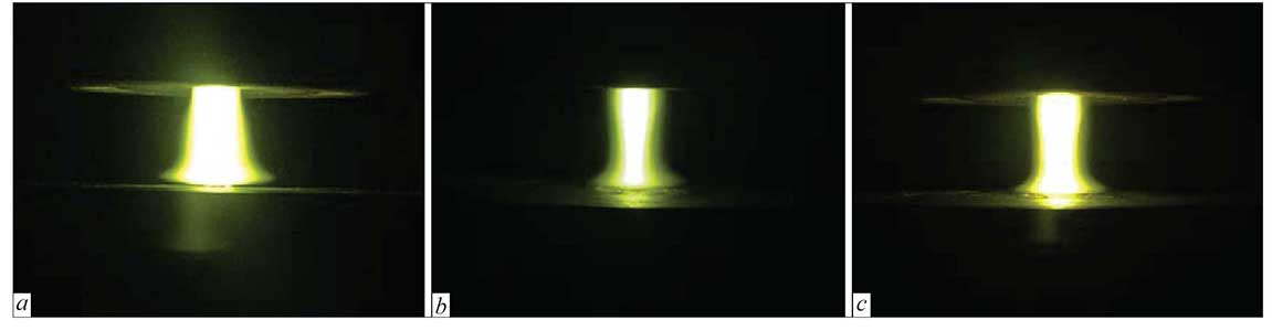
Figure 6. Appearance of arc columns at internal (a), external (b) and combined (c) schemes of powder feed
(Open image in full size: )
In order to neutralize this harmful impact, in this
PTA torch a gas flow is used, which is blown into the
central orifice of the focusing nozzle, similar to transport
gas feeding with internal system of powder feed.

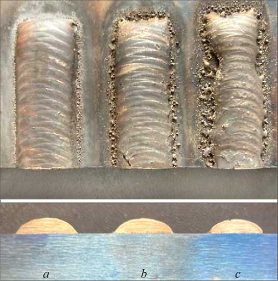
Figure 7. Appearance and cross-section of beads deposited in the same modes at different schemes of powder feeding into the arc: a — internal; b — external with stabilizing gas; c — external without stabilizing gas. Surfacing mode: Ia = 160 A; Vd = = 80 mm/min; Gf = 16 g/min; Qst.g = 4 l/min, deposited material is 304 stainless steel
(Open image in full size: )

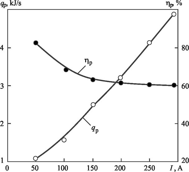
Figure 8. Dependence of powder losses on stabilizing gas flow rate at different bead width b: 1 — 10; 2 — 20 mm
(Open image in full size: )
Bead fullness is also increased, which is a confirmation of smaller powder losses (Figure 7, b). As shown in Figure 8, the maximal effect is achieved at stabilizing gas flow rate of 4‒5 l/min. This is valid both for narrow (curve 1), and for broad (curve 2) beads. A further increase of its flow rate no longer enhances the positive effect.
Thermal characteristics


Figure 9. Dependence of effective thermal power qp and effective efficiency of part heating ηp on arc current in the developed PTA torch
(Open image in full size: )
Thermal characteristics of the developed PTA torch were studied by the method of flow calorimetry on a model sample by a procedure described in [3]. Attention was focused on investigation of effective thermal power and effective efficiency of part heating for the given design of the nozzle part of the PTA torch. Investigations were conducted without the indirect (pilot) arc.
Figure 9 showed that the dependence of effective thermal power qp and effective efficiency of part heating ηp on arc current for a combination of plasma and focusing nozzles of 4/8 mm at flow rates of plasma (2 l/min), transport (4 l/min) and shielding (8 l/min) gases, characteristic for plasma surfacing.
One can see that with increase of arc current qp grows practically linearly, but ηp decreases. In the range of currents of 50‒250 A, it decreases from 80 to 60 %, which is related to increase of heat losses at the nozzle. On the whole, this index is sufficiently high, close to those for welding and cutting PTA torches [8].
CONCLUSIONS
- Combination of internal and external schemes of powder feeding into the arc in one PTA torch significantly widens its technological capabilities, as it allows surfacing of magnetic and nonmagnetic materials with a high efficiency and productivity.
- Additional flow of stabilizing gas with the external scheme of powder feeding reduces the harmful influence of cold flows of transport gas and lowers the powder losses by 10‒15 % due to its more effective heating. Optimal flow rate of stabilizing gas is equal to 4‒5 l/min.
- Developed PTA torch ensures a high enough efficiency of part heating. It is not lower than 60 % at maximal currents.
REFERENCES
- Gladky, P.V., Pavlenko, A.V., Zelnichenko, a.t. (1989) Mathematical modeling of heating of powder in arc during plasma surfacing. Avtomatich. Svarka, 11, 17–21, 54 [in russian].
- Dilthey, U., Ellermeier. J., Gladkij, P., Pavlenko, A.V. (1993) Kombiniertes Plasma-Pulver-auftragschweissen. Schweissen und Schneiden, 5, 241–244.
- Som, A.I. (1999) new plasmatorches for plasma-powder surfacing. Avtomatich. Svarka, 7, 44–48 [in russian].
- Som, A.I. (2015) Effect of scheme of powder feeding into arc on its losses and efficiency of plasma-powder surfacing process. The Paton Welding J., 5‒6, 22‒25.
- Som, A.I., Halahuz, B.A. (2020) Plasma transferred arc surfacing of composite alloys with separate feed of tungsten carbides and matrix alloy. The Paton Welding J., 12, 34‒39. DOI: https://doi.org/10.37434/tpwj2020.12.05
- Gladky, P.V., Pereplyotchikov, E.F., Ryabtsev, I.A. (2007) Plasma surfacing. Kyiv, ekotekhnologiya [in russian].
- Sidorov, A.I. (1987) Restoration of machine parts by spraying and surfacing. Moscow, Mashinostroenie [in Russian].
- Stikhin, V.A., Patskevich, I.R. (1967) Determination of thermal characteristics of constricted arc. Svarochn. Proizvodstvo, 9, 26–27 [in russian].