Centrifugal plasma surfacing of drill pump bushings
O.I. Som
The Paton Welding Journal. - 2022.
- №4. - pp. 14-18.
Features of centrifugal plasma surfacing using powders of three different alloying systems based on iron and nickel were studied. It is found that at centrifugal plasma surfacing the iron-based test powder has the best welding-technological properties. It allows producing deposited metal of 200Kh15D2MS2R type. The layer deposited with this powder, has a microstructure of uniform height and ensures increase of the sleeve wear resistance 5–6 times, compared to batch-produced ones, which are made from steel 70 and quenched by HFC. A design of the bushing component is proposed with replaceable surfaced sleeve, which is more adaptable to fabrication and allows repairing it by simple replacement of the worn sleeve.
centrifugal plasma surfacing, surfacing alloys, deposited metal, metal structure, wear resistance, carbides, hardness, layer thickness
Drilling pumps are used in oil and gas industry for well washing during drilling [1]. Maintaining the high pressure and required flow rate of the solution for washing in the well depends predominantly on reliable operation of the cylindrical bushing-piston pair. Unfortunately, because of the high content of abrasive particles in the solution, the cylindrical bushings quickly wear and fail.
Bushings are made from 70, 95Kh18, Kh12MF tool steels. Steel 70 is the most common as the most accessible and inexpensive. However, bushings made from this steel only last 150-200 h before they go out of service, which is obviously not enough. Different methods are used to strengthen the bushing working surface, in order to increase the bushing wear resistance. Hardening with high frequency currents (HFC) is the most widely used in practice [2, 3].
Bimetal bushings are also used, which were produced by centrifugal casting. The working layer from high-chromium cast iron ChKh28 15–20 mm thick, which is formed at pouring, is hardened by HFC to hardness HRC 62-65. The service life of such bushings reaches 600-800 h that is quite acceptable in most cases [4]. Also known is application of bushings with a ceramic insert, which ensures the operating time of up to 3000 h. They, however, are very expensive and are very seldom applied [5].
PWI proposed application of the method of centrifugal plasma surfacing (CPS) to increase the bushing wear resistance [6, 7]. The essence of this method consists in surface melting of a layer of filler powder, which is predeposited on the surface of the processed part by the direct plasma arc, burning in argon between the nonconsumable tungsten electrode and the item. During surfacing the part rotates at a certain speed in the upgraded lathe chuck (Figure 1).

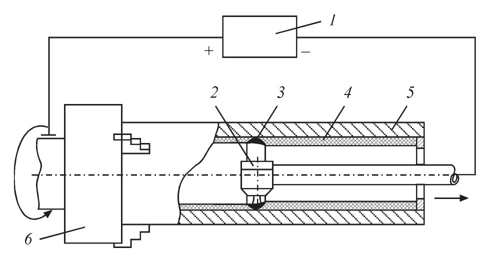
Figure 1. CPS diagram: 1 — power source; 2 — plasmatron; 3 — circular weld pool; 4 - fi11er powder; 5 — part; 6 — lathe chuck
The main advantage of CPS is the possibility of deposition of relatively thin (2.5-3.0 mm) layers of wear- and corrosion-resistant material with a high productivity and smooth surface that allows minimizing the machining. However, at CPS a structural heterogeneity by height (thickness) of the deposited layer can develop as a result of the possible different specific density of the structural components of the deposited metal. Such a structural heterogeneity can have a negative effect on the deposited metal service properties.
The objective of the work consists in selection of wear-resistant powders, suitable for centrifugal plasma surfacing of the bushings, studying their welding-technological properties, microstructure and wear resistance of the deposited layers. It was also necessary to develop the design of the bimetal bushings, perform their surfacing and subsequent experimental-industrial testing under different climatic conditions.
MATERIALS AND PROCEDURES FOR CONDUCTING EXPERIMENTS AND INVESTIGATIONS
Selection of powders for surfacing was based on the technological features of CPS method, and requirements made of the deposited layer of the bushings. The deposited metal meeting these requirements, should be resistant to abrasive and hydroabrasive wear, cavitation, and should have high enough corrosion resistance and casting properties.
Three powders were selected for studying and surfacing the test bushings, which ensure producing wear-resistant nickel- and iron-based alloys (see Table).
Chemical composition of the studied types of the deposited metal
| Number | Type of deposited metal (powder grade) | Weight fraction of elements, % | |||||||
| C | Si | В | Cr | Ni | Fe | Mo | Others | ||
| 1 | N75Kh15S4R4(PG-SR4)* | 0,74 | 3,25 | 3,74 | 16,2 | Base | 2,1 | – | – |
| 2 | 250Kh30S2R(PG-AN1)* | 2,21 | 2,15 | 1,61 | 29,6 | – | Base | - | 2,08 Мn |
| 3 | 200Kh15D2MS2R (test) | 2,24 | 2,43 | 1,31 | 14,9 | – | Base | 1,15 | 2,12 Cu0, 0,48 Al–Ce |
| *Made to GOST 21448-75 [8]. | |||||||||
Alloy No. 1 is well-known self-fluxing nickel-based alloy. It has a high wear-resistance, low melting temperature (1050-1100 °C) and excellent casting properties.
Alloy No. 2 is a high-chromium cast iron, which is additionally alloyed by boron to improve the wear resistance and casting properties.
Alloy No. 3 is an iron-based experimental alloy, specially developed for CPS, taking into account the technological features of this surfacing method. It is additiona11y a11oyed by 0.5 % a1umocerium for refining its structure.
The welding-technological properties of the powders were studied at surfacing samples in the form of thick-walled bushings, which simulate the real parts. Bushing dimensions are as follows: inner diameter of 100 mm, outer diameter of 160 mm and length of 200 mm. Surfacing modes were selected, taking into account the investigation results [6, 9]. The evaluation criterion was the number of cracks in the deposited layer, presence of unevenness, slagging and pores on its surface, as well as a metallurgical bond between the main and deposited metal. The samples cut out of these bushings were used for investigation of the microstructure, hardness and wear resistance of the deposited metal.
 of metal deposited by centrifugal plasma method: a — deposited metal N75Kh15S4R4; b — deposited metal 250Kh30S2R; c — test deposited metal 200Kh15D2MS2R")

Figure 2. Microstructure (×320) of metal deposited by centrifugal plasma method: a — deposited metal N75Kh15S4R4; b — deposited metal 250Kh30S2R; c — test deposited metal 200Kh15D2MS2R
(Open image in full size: )
INVESTIGATION RESULTS AND THEIR DISCUSSION
Investigations of the surfaced samples showed that all the three powders ensure good formation of the deposited metal. The deposited layer surface is quite smooth with a slight oxide film build-up which can be easily removed. Pores and slagging are absent.
However, longitudinal cracks were detected in the deposited metal of all the three types. Their greatest number (3) of them was in deposited metal No. 2. They could not be avoided, either by increase of surfacing heat input, or preheating application. Appearance of cracks could be completely avoided only due to reduction of the bushing wall thickness to 15 mm. In this case they are more uniformly preheated and become less rigid.
At CPS, formation of the deposited metal structure has its features. The deposited metal layer forms at slow cooling and under the conditions of the action of considerable centrifugal forces (up to 50 g), which may lead to structural heterogeneity by deposited layer thickness, as a result phases liquation, because of their different density.
Microstructural studies of deposited metal No. 1 and No. 2 showed that two zones can be distinguished in them: a eutectic one of 0.3-0.4 mm length at the fusion line and hypereutectic one with large primary carbides and chromium carboborides in the middle and upper zones of the deposited layer (Figure 2, a, b). These carbides as lighter ones, are driven upwards and are located in the direction of heat removal. No noticeable structural heterogeneity was revealed in deposited metal No. 3 (Figure 2, c). The microstructure is of a eutectic nature along the entire thickness of the layer without any large primary carbides or chromium carboborides.
 and wear resistance (b) distribution by the thickness of the layer deposited
by the centrifugal method by PG-SR4 (1), PG-AN1 (2) powders and test powder (3)")
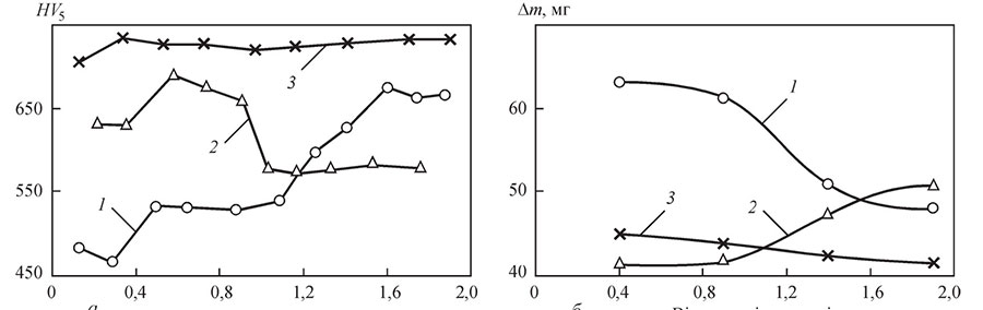
Figure 3. Hardness (a) and wear resistance (b) distribution by the thickness of the layer deposited by the centrifugal method by PG-SR4 (1), PG-AN1 (2) powders and test powder (3)
(Open image in full size: )
The eutectic and hypereutectic zones of deposited metals No. 1 and No. 2 differ also by their hardness. In deposited metal No. 1 it increases in the direction towards the surface, and in the deposited metal No. 2, it, contrarily, decreases (Figure 3, a, curve 1 and 2). Unlike that, hardness across the thickness of deposited layer No. 3 is stable (Figure 3, a, curve 3). It is equal to HV5 700-720.
Considering the structural heterogeneity of the deposited metal across the deposited metal thickness, the wear resistance of each of its zones was studied separately. For this purpose the layer was ground to different depth with a step of 0.5 mm. Testing conditions were selected so that linear wear of the sample in the studied zone did not exceed the above-given value. Testing was conducted in NK-M machine [10]. Testing parameters were as follows: sliding speed of samples of 0.6 m/s; mean specific pressure per sample of 0.5 MPa, friction path of 400 m. Quartz sand was used as abrasive. Test results are given in Figure 3, b.
As we can see, wear resistance of deposited metal Nos 1 and 2 differs in different zones, although insignificantly (15-20 %). It is in a certain correlation with hardness, i.e. with hardness increase in the hypereutectic zone for alloy No.1 the wear resistance becomes higher, and with its decrease for (alloy No. 2) it also decreases.
Wear resistance of the studied deposited metal No. 3, similar to its hardness, is at a very high level across the layer thickness, and changes only slightly, making this type of deposited metal a highly promising material for CPS of bushings.

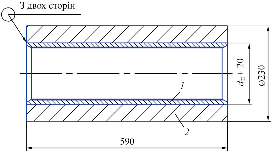
Figure 4. Design of the composite bushing of U8-6MA2 drill pump with the surfaced sleeve: 1 — surfaced thin-walled sleeve; 2 — case
EXPERIMENTAL-INDUSTRIAL VERIFICATION OF INVESTIGATION RESULTS
Proceeding from the conducted studies, powders Nos 1 and 3 were selected for surfacing the test parts, which showed the best results as to wear resistance. When manufacturing the bushings, the design of a composite bushing was realized, which consists of a thick-walled case and thin-walled surfaced sleeve, which is put into it by a hot fit (Figure 4).
The case and sleeve material is steel 20. The bushing components, despite the higher labour content of their manufacturing, have several advantages, compared to monolithic ones:
- surfacing a thin-walled sleeve (10-12 mm) is less energy-consuming, simpler in terms of prevention of cracks in the deposited layer and more efficient;
- compressive stresses, developing in the deposited metal at sleeve pressing, are favourable for its serviceability, as they lower the tensile stresses, arising at bushing operation under the impact of inner working pressure;
- composite bushings are repairable due to the possibility of replacement of the worn bimetal sleeve by a new one, while preserving the old thick-walled case that allows saving a lot of metal and lowers the labour cost.

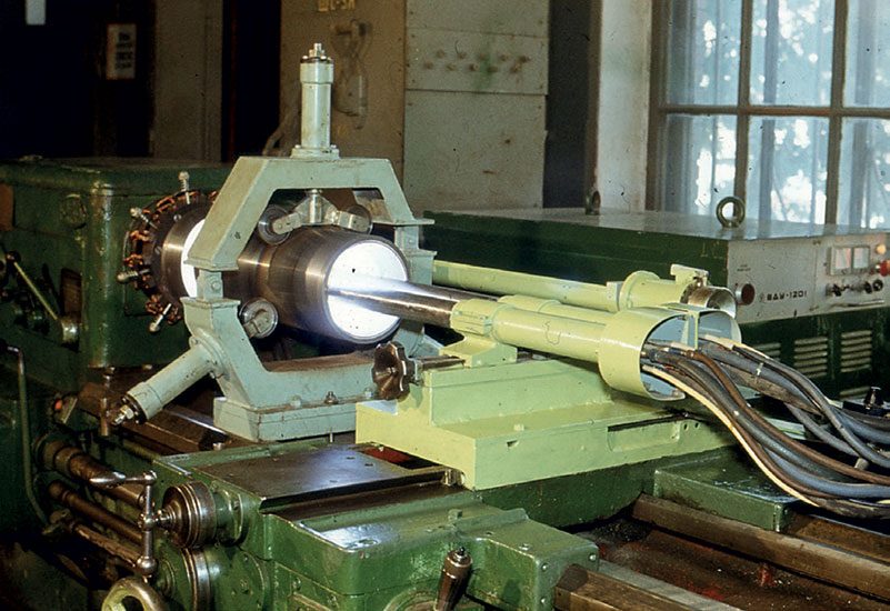
Figure 5. UD-251 experimental unit for CPS
(Open image in full size: )
Surfacing the test sleeve billets was performed in UD-251 machine, which is based on a lathe, with two plasmatrons simultaneously (Figure 5).
The deposited layer thickness was selected, proceeding from the extent of admissible wear, machining allowance and billet shrinkage, resulting from their heating at surfacing. Average thickness of the deposited layer was in the range of 2.5-3.0 mm, after grinding it was 1.5-2.0 mm. At the first stage 10 bushings for U8-6MA2 pump were made, of which 4 bushings of 180 mm diameter were surfaced by powder of alloy No. 1, and 6 bushings of 160 mm diameter — by powder of alloy No. 3. A sample of the surfaced bushing with partial grinding is shown in Figure 6.

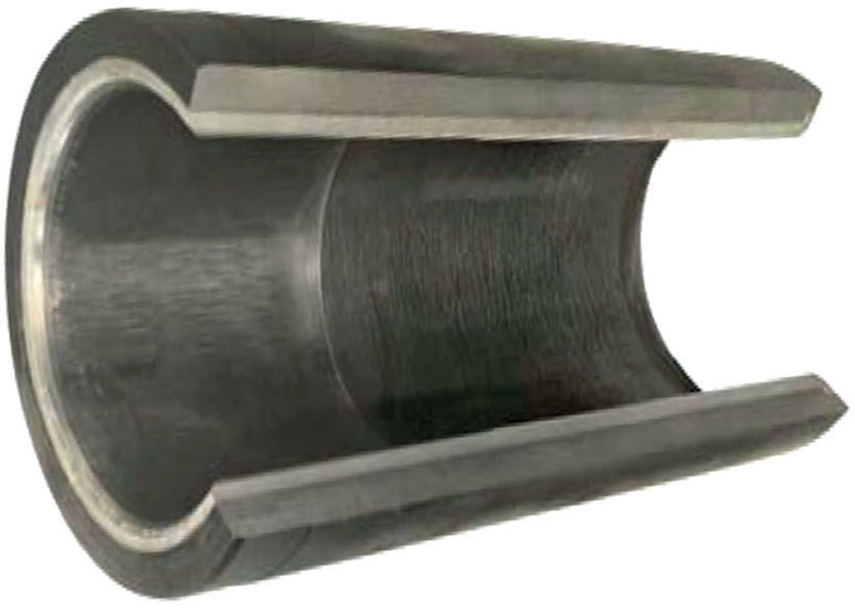
Figure 6. Appearance of a surfaced bushing of 160 mm diameter
(Open image in full size: )
 and 200Kh15D2MS2R (2)")
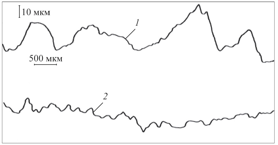
Figure 7. Profiograms of worn surfaces of dri11 pump bushings, surfaced by powders of N75Kh15S4R4 (1) and 200Kh15D2MS2R (2)
Comparative testing of the surfaced and batch-produced bushings showed that the nickel-based deposited metal No.1 (N75Kh15S4R4), despite its rather high hardness HRC 59, has low resistance, particularly at higher pressure of the washing solution. After 100 h of operation at turbine drilling the bushing wear was 0.6 mm per side. Deep longitudinal scratches were detected on the deposited layer surface (Figure 7, a), as well as cavitation damage centers
.More over, the piston rubber collars failed very quickly at operation in a pair with this alloy (Figure 8). The pistons had to be replaced every 20 h of operation, whereas in a pair with batch-produced bushings they last 70-80 h. The cause for such a phenomenon can be the low heat conductivity of the nickel alloy, causing poor heat removal from the friction zone of the rubber collar and deposited working layer of the bushing. Under these conditions, the rubber has enough time to heat up to destruction temperature and fail.

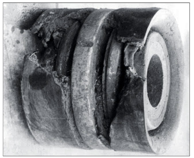
Figure 8. Appearance of the piston with rubber collars after studying a bushing deposited with powder of N75Kh15S4R4 alloy
(Open image in full size: )
Bushings, which were surfaced by powder of iron-based test alloy (200Kh1502MS2R) showed quite high resistance. Average operating life is equal to 1150-1200 h that is 5-6 times higher that the resistance of batch-produced parts under these conditions. Some of the parts after 1200 h of operation did not exhaust their expected useful life and were removed from testing, due to completion of drilling operations. Investigation of working surfaces of the bushings after testing showed that they also have longitudinal scratches. However, the microroughness height is much smaller than in the two previous cases (Figure 7, b). No "flushing", characteristic for batch-produced bushings, was observed on any of the surfaced bushings. It should be also noted that the service life of the pistons in a pair with bushings, surfaced by powder of test alloy No. 3, is 1.5-2.0 times higher, compared to batch-produced bushings, that is, probably, attributable to more favourable microrelief of the working surface and higher heat conductivity of the working layer.
Several more batches of the bushings surfaced by the test alloy powder, were manufactured and tested which also confirmed their high serviceability.
CONCLUSIONS
- Centrifugal plasma surfacing is an efficient method to improve the pump bushing wear resistance. Optimum thickness of the deposited layer, proceeding from the service conditions and machining allowances, is 2.5–3. 0 mm.
- Test powder 200Kh15D2MS2R was proposed, which completely meets the needs of centrifugal plasma surfacing and ensures high wear resistance of the metal deposited with this powder. Drill pump bushings, surfaced with this powder, during performance of work in West Ukraine, demonstrated 5–6 times higher resistance, than batch-produced ones, made of steel 70 and strengthened by HFC hardening. Increase of resistance of pistons with rubber collars 1.5–2.0 times was also noted here.
- he developed design of a composite bushing with a replaceable sleeve is quite efficient techno logically and ensures a high performance of the drill pump. Owing to repair possibilities it allows saving a considerable quantity of the deficit metal.
REFERENCES
- Nikolich, A.S. (1973) Drill piston pumps. Moscow, Nedra [in Russian].
- Mkrtychyan, Ya.S. (1984) Improvement of ef.ftciency of drill pump units. Moscow, Nedra [in Russian].
- Samoilovich, Yu.A. (2017) Increase of operating life of drill pump barrel by thermocyclic treatment of barrel material. Stal, 4, 44–49 [in Russian].
- Site LLC Bursnab. http://www.bursnab.com, Moscow [in Russian].
- Site LLC RosPrombur. http://www.rosprombur.ru, Moscow [in Russian].
- Gladky, P.V., Som, A.I., Pereplyotchikov, E.F. (1984) Centrifugal surfacing. In: New processes of surfacing, properties of deposited metal and transition zone. Kyiv, PWI, 31-34 [in Russian].
- Yushchenko, K.A., Gladky, P.V., Som, A.I. et al. (1991) Method of centrifugal surfacing. USSR author’s cert. 1636151. Publ. 23.03.1991 [in Russian].
- (1979) Surfacing materials of countries-members of CMEA. Catalog. MTsNTI [in Russian].
- Som, A.I., Zelnichenko, A.T. (2010) Numerical calculation of thermal processes in centrifugal plasma powder cladding. The Paton Welding J., 6, 13-18.
- Yuzvenko, Yu.A., Gavrish, V.A., Marienko, V.O. (1979) Laboratory units for evaluation of wear resistance of deposited metal. In: Theoretical and technological principles of surfacing. Properties and tests of deposited metal. Kyiv, PWI, 23–27 [in Russian].