Plasma transferred arc surfacing of composite alloys with separate feed of tungsten carbides and matrix alloy
A.I. Som and B.A. Halahuz
THE PATON WELDING JOURNAL, No. 12, 2020. - pp. 34-39.
Various combinations of separate feeding of cast spherical tungsten carbides and matrix alloy into the surfacing zone have been investigated. It has been established that when a self-fluxing nickel-based alloy is used as a matrix, the most stable surfacing process is achieved if tungsten carbides are fed through the axial bore in the focusing nozzle, and the matrix alloy comes through two channels located diametrically opposite to each other at its end. Ref. 6, 1 Table, 11 Figures.
Keywords: plasma transferred arc surfacing, tungsten carbides, spherical tungsten carbides, self-fluxing alloy, matrix, carbide distribution, wear resistance, microhardness
Plasma transferred arc surfacing (PTA surfacing) of composite alloys based on cast tungsten carbides (furtheron referred to as spherical tungsten carbides (carbides)) is ever wider used in industry to improve the wear resistance of parts operating under the conditions of intensive abrasive wear [1, 2]. A mixture of powders consisting of 40 % carbides and 60 % matrix alloy (by volume) is mainly used as filler material for surfacing. By mass, the proportions are approximately the same, but just reversed. As a rule, the matrix alloys are low-melting self-fluxing nickel-based alloys with different degree of alloying by Cr, Si, B and C. Matrix hardness here varies in the range from HRC 20 up to HRC 60. The above quantity of carbides is considered to be optimal, ensuring good formation and high wear resistance of the deposited metal, although mixtures with an even high content of carbides are sometimes used in practice. They can be of a fragmentary or spherical shape. Surfacing is performed predominantly using PTA torch with external feed of powders through one or several channels [3]. The fraction of powders in the mixture usually is 63–160 μm.


Figure 1. Scheme of PTA surfacing with carbides feeding into weld pool tail part: 1 — electrode; 2 — plasma nozzle; 3 — focusing nozzle; 4 — shielding nozzle; 5 — part; 6 — ballast resistor; 7 — power source; 8 — arc ignition block
To achieve maximum wear resistance of the deposited layer, it is highly important for the carbide particles to be uniformly distributed in the deposited bead, both over the cross-section, and by its length. This, in its turn, is largely dependent on uniform distribution of carbides in the powder mixture used for surfacing. Unfortunately, it is difficult to ensure it in practice, as separation of carbides and matrix alloy takes place, because of the large difference in their density (approximately 2:1). This is particularly evident at application of mixtures with carbides. In some areas we can observe an excess of carbides, and in other areas, on the contrary, a lack of it. In the areas of carbide accumulation, violation of the deposited bead formation takes place, because of a lack of the low-melting matrix, and cracking is probable. This disadvantage can be avoided, by applying separate feed of carbide powders and matrix alloy from separate feeders-dispensers.
In this case, their required ratio can be accurately maintained during the entire surfacing process. In this paper the possible schemes of separate feed of powders are considered, and their advantages and disadvantages are analyzed. Investigations were performed using experimental and batch-produced PTA torch of Plasma-Master Co., Ltd.. Used as filler materials were carbides produced by Resurs-1 Ltd, Ukraine and powder of nickel-based alloy of 315-R2 grade of Wall Colmonoy Company, US with HRC 32 hardness. The fraction of carbides and Ni-alloy powders was 100–200 and 63–100 μm, and their ratio at feeding was 40 and 60 vol.%, respectively.
Carbides [4] is a highly convenient material for plasma surfacing with separate feed. It has excellent flowability, can be readily dosed, and compared to crushed carbides, it wears the channels in the PTA torch much less.
")
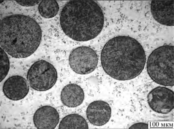
Figure 2. Shape and arrangement of carbide particles in the matrix at its feed into weld pool tail part (×200)
Surfacing of test samples was performed on plates from steel 20. Bead width was 20–22 mm, its height was 4.0–4.5 mm, and deposition rate was 4 kg/h. Samples were cut out of the surfaced plates for metallographic investigations and for wear resistance testing by SR («stationary ring») procedure [5]. In the latter case, the upper part of the deposited metal layer was ground to the level, where the carbide grains were relatively uniformly distributed over the section. Investigations were performed at PWI.
Figure 1 shows the schematic of PTA surfacing with separate feed, where the matrix alloy powder is fed into the arc through the axial bore of the PTA torch focusing nozzle in the form of a distributed flow, and carbides flow through a separate channel directly into the weld pool tail part. The idea of this scheme consists in that the carbide particles did not penetrate under the arc, and were in contact with the weld pool molten metal for as short time as possible. This allows avoiding their melting or dissolution, preserving them in their initial form, and, consequently, providing the maximum wear resistance of the deposited metal.
Realization of this scheme mainly confirmed the assumptions made. Carbide particles are well preserved, the interfaces are very clear-cut (Figure 2). Their microhardness is maximal and is equal to HV01 – 2200– 2400 Pa. Matrix microhardness is stable by the entire height of the layer and it is close to that of metal, deposited without carbides (HV01 – 327–380).This is indicative of the fact that dissolution of carbide particles is practically absent, and the matrix is not enriched with carbon or tungsten, which significantly influence the microhardness. The wear resistance of metal, deposited by this scheme, is also maximal (Table).
Filler powder losses and wear resistance of metal deposited by different schemes of carbides feeding into the weld pool
| Number | Scheme of spherical tungsten carbides feeding into the weld pool | Volume ratio of carbides and matrix alloy, % | Total powder losses, % | Wear resistance, SR (mass loss), g |
| 1 | Into tail part (Figure 1) | 40/60 | 12‒15 | 0.035 |
| 2 | Through two channels parallel to bead axis (Figure 3, a) | 40/60 | 8‒10 | 0.045 |
| 3 | Through two channels normal to bead axis (Figure 3, b) | 40/60 | 10‒12 | 0.050 |
| 4 | Through axial bore in the form of mixture (Figure 5) | 40 /60 | 2‒3 | 0.035 |
| 5 | Through axial bore (Figure 6) | 40/60 | 3–5 | 0.040 |
| 6 | Through axial bore (Figure 6) | 50/50 | 4–6 | 0.045 |


Figure 3. Schemes of PTA surfacing with carbides feeding into the weld pool head part through two channels: a — channels are located in the plane parallel to deposited bead axis; b — normal to axis
(Open image in full size: )
This scheme, however, has a number of significant disadvantages. These are unsatisfactory formation of the deposited bead, large carbide losses and high level of internal stresses. Point is that the cold carbide particles «freeze» the weld pool. Its volume decreases and a considerable part of carbides (12–15 %) does not penetrate into it and is lost. Carbides is located mainly in the bead middle part that results in its convex shape. Internal stresses arise on the interface of carbides with the matrix, because of the large difference in the coefficients of thermal expansion. At surfacing of massive parts this can lead to appearance of microcracks and cause spalling of deposited metal, particularly at application of hard matrices.

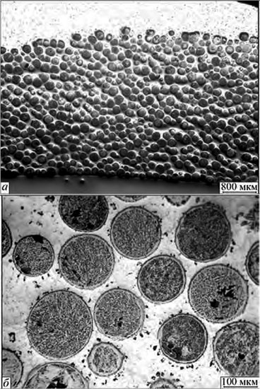
Рис. 4. Распределение и форма частиц релита при подаче через два канала, расположенных диаметрально противоположно друг к другу в торце фокусирующего сопла: а – ×25; б – ×200
(Open image in full size: )
The schemes of carbides feeding into the pool head part from two channels located diametrically opposite to each other in the end part of the focusing nozzle give the best result. This is true in the case of feed channel location both in the plane parallel to the deposited bead axis (Figure 3, a), and normal to it (Figure 3, b).
To achieve the maximum effectiveness, the angle of carbide feeding and the distance from PTA torch end to the workpiece were selected so that the powder particles fell into the weld pool hottest zone near the arc anode spot. In this case, they are heated very well and do not noticeably cool down the weld pool. With a correctly selected surfacing mode, first of all, optimal arc current, well formed beads can be obtained at small losses of carbides (see Table). Contrary to expectations, the carbide particles do not have time to melt under the arc. They quickly sink to the weld pool bottom and are closely packed in its lower part (Figure 4, a). Just a white fringe of the decarbonized layer can be observed on the particle surface (Figure 4, b). Microhardness of carbide particles is the same as in the previous case. An unfilled layer of the matrix forms in the bead upper part, above the carbide layer.


Figure 5. Scheme of PTA surfacing with feeding carbides mixed with matrix powder inside the PTA torch distribution chamber
The smallest loss of carbides (see Table) and better formation of the deposited bead are ensured by a scheme, where carbides are mixed with the matrix alloy inside the PTA torch and penetrate into the weld pool together with them in the form of a distributed flow (Figure 5). A principal difference of this scheme from the previous ones consists in that carbides come to the weld pool in a heated state after passing through the arc. Due to that they do not cool the weld pool, but, on the contrary, increase its heat content that promotes their rapid distribution in the liquid metal. Despite the preheating of particles in the arc, as shown by experiments, the carbide particles do not have enough time to melt under the arc, as they immediately sink to the bottom. A layer of low-melting matrix forms on top, which protects them.


Figure 6. Scheme of PTA surfacing with feeding carbides into the weld pool through axial bore of focusing nozzle
Self-fluxing nickel-based alloys of Ni‒Cr‒Si‒B system are very convenient for application as a matrix alloy at surfacing with composite alloys. They have a low-melting temperature (1000–1100 °C), readily wet the carbide particles and have rather good inherent wear resistance. However, at plasma surfacing with these alloys, using PTA torch with internal powder feed [3] there are a number of technological difficulties, related to their low-melting temperature. Fine powder particles (up to 100 μm) which penetrate into the central high-temperature region of the arc have enough time to heat up to evaporation temperature during their flight [6]. Metal vapours deposit on the cold walls of the focusing nozzle, forming a kind of insulation interlayer in the form of accretion. This interlayer is growing steadily during surfacing, and a moment comes, when it starts melting, forming drops at the focusing nozzle outlet. These drops block powder outflow and, eventually, disrupt the surfacing process. Moreover, volatile fractions from the weld pool deposit on the focusing nozzle edge, forming a loose deposit with time, which, if not removed, also disrupts the surfacing process. This adverse phenomenon can be partially avoided, if a coarser powder (more than 100 μm) is used, but it cannot be eliminated completely, as a dust-like fraction (up to 5 %), which remains after screening, is always present in the powder.
")
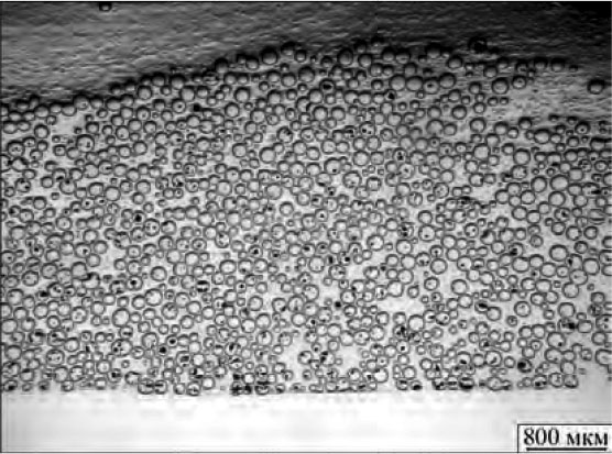
Figure 7. Carbide distribution in deposited metal at its feeding through axial bore of focusing nozzle (40 vol.%)
At external feeding through separate channels, the effectiveness of powder heating is much lower [6] and no filler powder drops form inside the focusing nozzle, although sticking of volatile fractions to its edge still takes place, but to a smaller degree. In this connection, the scheme of deposition of composite alloys presented in Figure 6, is the most preferable in terms of process stability. With this scheme, only carbides are fed into the weld pool through an axial bore of the focusing nozzle, and the matrix alloy comes through two diametrically opposite channels, i.e. conversely to earlier discussed schemes (Figure 3).

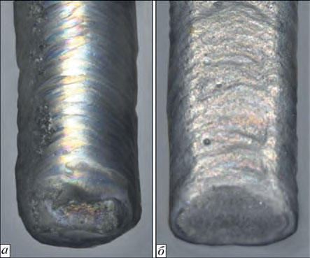
Figure 8. Appearance of beads deposited with carbide feeding through axial bore of focusing nozzle: a — 40; b — 50 vol.% of carbides
Carbides, as a higher melting material, do not have enough time to heat in the arc up to melting temperature during their flight, and, therefore, do not have any adverse influence on the surfacing process. Contrarily, preheating, similar to the previous case, promotes denser and faster distribution of carbide particles in the weld pool and lowering of internal stresses in the deposited metal. Carbide distribution by this feed scheme is shown in Figure 7.
As one can see, carbide particles are rather closely and uniformly arranged in the lower part of the deposited bead. Together with matrix alloy interlayers they take up approximately 2/3 of its cross-section. The bead upper part remains unfilled with carbides. It is natural that the wear resistance of this part is not high. However, excess amount of matrix alloy promotes good formation of the deposited bead (Figure 8, a), improves cracking resistance and is a kind of protection for carbide particles from dissolution under thermal impact of the arc.>
: a — ×25; b — ×200")
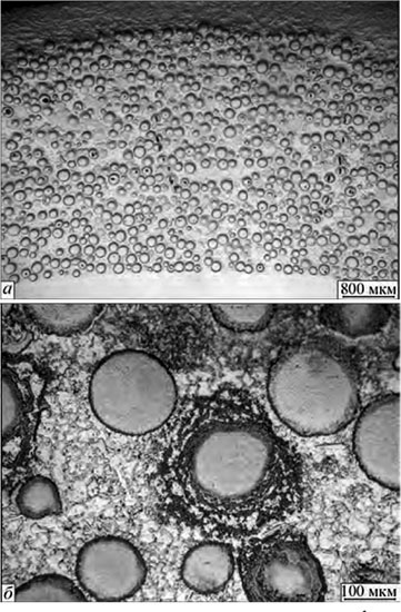
Figure 9. Distribution and shape of carbide particles in the deposited metal at their feeding through axial bore in focusing nozzle (50 vol.%): a — ×25; b — ×200
(Open image in full size: )
Additional experiments showed that with this scheme the carbide content in the filler material can be increased up to 50 vol.% without disturbance of the surfacing process, in order to improve the bead filling with carbides. The bead shape becomes more flat and favourable from the view point of wear resistance (Figure 8, b).
At the same time, metallurgical investigations showed (Figure 9) that with increase of carbide percentage some carbide particles start breaking up.
This is attributable to the fact that in this case the deposited bead is filled with carbides almost to the top, the protective layer of the low-melting matrix becomes insufficient and its particles now are on the surface under the concentrated plasma arc. Melting and dissolution of the carbide particles is further promoted by that the arc current also has to be increased with increase of the amount of carbides in the mixture, enhancing the thermal impact on the particles. It results in matrix enrichment in carbon and tungsten that leads to a certain increase of matrix hardness. In our case, this increase is small (up to HV01 – 400–420 Pa) andNo cracks were observed in the deposited layer. Wear resistance also remained on the same level. This leads to a practical conclusion.

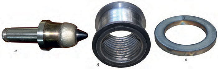
Figure 11. Examples of parts surfaced with composite alloy: a — cutter of coal cutter-loader; b — crushing equipment case; c — pump stabilizing ring
(Open image in full size: )
If machining of the deposited layer is required after surfacing to achieve an exact geometrical size, then it is better to deposit the bead so that it is not completely filled with carbides. This facilitates machining, and reduces the consumption of expensive carbides, without lowering the wear resistance of the working layer as a whole. Now if no machining is required by operation conditions, carbide content in the mixture should be increased up to 50 vol.%, and high wear resistance should be ensured by the entire thickness of the deposited layer.
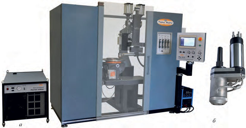
Figure 10 shows equipment for PTA surfacing with composite alloys with separate powder feed, and Figure 11 gives examples of the surfaced parts.
Conclusions
- At PTA surfacing with composite alloys with separate powder feed the most effective is the scheme, where carbides are fed through the axial bore of the focusing nozzle, and the matrix alloy comes through two diametrically opposite channels, located in its end.
- To ensure more uniform wear resistance of the deposited layer by height, the volume fraction of carbides can be increased up to 50 % at feeding without violation of the surfacing process.
References
- Harper, D., Gill, M., Hart, K W. D, Anderson, M. (2002) Plasma transferred arc overlays reduce operating costs in oil sand processing. In: Proc. of Int. Spray Conf. YTSC 2002 (Essen, Germany, May 2002), 278–283.
- Som, A.I. (2004) Plasma-powder surfacing of composite alloys based on cast tungsten carbides. The Paton Welding J., 10, 49–53.
- Som, A.I. (1999) New plasmatrons for plasma-powder surfacing. Avtomatich. Svarka, 7, 44‒48 [in Russian].
- Zhudra, A.P. (2014) Tungsten carbide based cladding materials. The Paton Welding J., 6–7, 66‒71.
- Yuzvenko, Yu.A., Gavrish, V.A., Marienko, V.Yu. (1979) Laboratory units for evaluation of wear resistance of deposited metal. Theoretical and technological principles of surfacing. Properties and tests of deposited metal. Kiev, PWI, 23‒27 [in Russian].
- Gladky, P.V., Pereplyotchikov, E.F., Ryabtsev, I.A. (2007) Plasma surfacing. Kiev, Ekotekhnologiya [in Russian].