Repair of screws of extruders and automatic molding machines by PTA surfacing
A.I. SOM
THE PATON WELDING JOURNAL, No. 4, 2019
The peculiarities of formation of a bead on narrow tip of screw flight in PTA surfacing were investigated. It is shown how a shape of deposited bead depends on its section and main technological parameters of surfacing, i.e. arc current, surfacing speed and PTA torch zenith displacement. The nomograms for selection of surfacing mode parameters were proposed. Equipment and consumables used for surfacing are also described. Repair of screws of extruders and automatic molding machines using PTA surfacing allows repairing these parts as well as 3–5 times increasing their service life in comparison with new nitrated screws. 11 Ref., 13 Figures.
Keywords: PTA surfacing, screws of extruders and automatic molding machines, narrow tip, bead formation, surfacing parameters, equipment and consumables
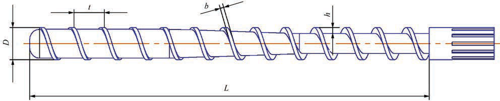
In process of operation the screws of extruders and automatic molding machines are subjected to intensive wear-out, in particular, during processing of composite plastics with fillers having abrasive effects. Wear of these parts takes place mainly on the flight tips, which resulted in increase of working gap between the screw and cylinder and, as a consequence, drop of productivity of screw extruder in whole. Regardless nitration, which is used to raise wear resistance, their service life in a series of cases does not exceed 6–8 months. These parts are complex on design (Figure 1) and expensive, therefore, repair and increase of their service life is a very relevant problem.
The most efficient method for repairing the screws is surfacing of a thin layer (1–2 mm) of wear- and corrosion resistant alloy on flight tip. The best for this is a method of PTA surfacing (PTAS), which due to its technological peculiarities allows providing excellent formation of deposited bead at minimum melting of flight tip [1–5].
Surfacing on flight tip of screw is sufficiently difficult technological problem due to design peculiarities of these parts. First of all, this is a large relationship of length to diameter reaching in modern machines 30, and the varying sizes of flights on part length, namely width and height. The surfacing is also complicated by wide range of screws, in which diameter can be changed from 20 to 300 mm, length from 600 to 600
 and
shape of deposited beads at small (b) and close to optimum (c)
cross-section area")
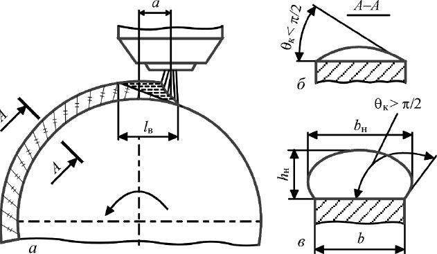
Figure 2. Scheme of surfacing on tip of screw flight (a) and shape of deposited beads at small (b) and close to optimum (c) cross-section area
Earlier E.O. Paton Electric Welding Institute and then Plasma-Master Ltd with participation of the author of this paper have carried the large complex work on optimizing the PTAS process of screws with development of special surfacing alloys and equipment. Surfacing in repair of screws shall be performed directly on flight tip, i.e. on the surface with limited width and large curvature. Under these conditions it is very difficult to provide set size and shape of bead, in particular, in surfacing of parts of small diameter (20–40 mm), having flight width only 3–4 mm. In order to solve this problem it was necessary to investigate the peculiarities of bead formation on narrow substrate and set the relationship between its shape and main technological parameters of the process of plasma surfacing.
Formation of bead on flight tip of screw. Cross-section profile of deposited bead is formed under effect of many factors, namely surface tension of weld pool metal, gravity force, arc pressure, etc. [6–8]. The main peculiarity of formation lies in the fact that bead width in its bottom always equals to a flight width (Figure 2).

In this case the most important parameter, which determines a bead shape, is its fullness, i.e. cross-section area Ss. Rise of Ss provokes increase of height hs as well as change of coefficient of bead shape K (K = bs/hs) and angle of bead contact with substrate qc (Figure 3).
Bead shape becomes more favorable from point of view of machining allowances (bs > bb), but there is rise of danger of dripping of weld pool metal in the process of surfacing. Therefore, in surfacing with free formation of bead section its height, respectively, can be increased only to some level depending on width of flight screw bead and metal capillary constant of the weld pool metal.


Figure 4. Optimum cross-section areas Ss.o and height hs.o of deposited bead for different width of flight tip b
Figure 4 shows the optimum for deposited metal of 220Kh18FM2N3 [9, 10] type values of Ss.o and hs.o at which favorable formation of beads is provided (qc > > 90°; bs > b) and there is no dripping of weld pool liquid metal in side directions. However, bead cross-section at this flight width ambiguously determines its shape. The latter in many respects depends on technological parameters of the process, i.e. arc current Ia, surfacing rate Vs, arc zenith displacement a (Figure 1, a), etc.
Base metal penetration in PTA surfacing on the optimum modes is insignificant [11], therefore cross-section area of beads is proportional to value of relationship of powder feed Gf to surfacing rate Vs. Keeping this relationship constant it is possible to obtain deposited beads with set Ss at different deposition rate of surfacing process. However, increase of filler powder feeding requires increase of arc current, that, in turn, results in rise of weld pool length (Figure 5).

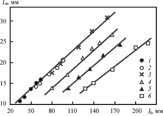
Figure 5. Dependence of weld pool length Lp on arc current Ia in tip width b [6]: 1 — b = 4; 2 — 5; 3 — 7; 4 — 10; 5 — 15; 6 — 20 mm
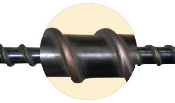
As can be seen from Figure 5, length of weld pool is particularly large at small width of flight (up to 8 mm), when surfacing is performed without transverse oscillations of PTA torch on relatively high currents. If length of the weld pool reaches critical value Lcr for this diameter of part D, the process of surfacing is disturbed because of dripping of liquid metal (Figure 6), which can not be prevented due to arc zenith displacement. Based on our data Lcr = (0.22–0.26)/D.
 and more (b); d = 90 mm; b = 7 mm")
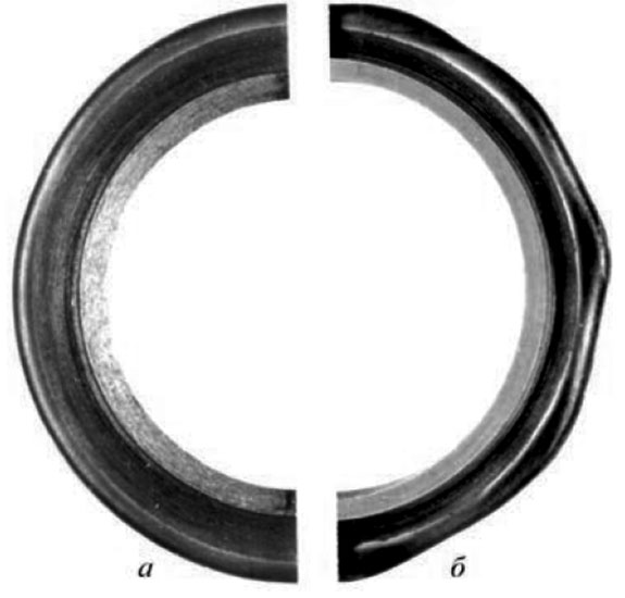
Figure 6. Appearance of deposited beads at pool length less than critical (a) and more (b); d = 90 mm; b = 7 mm
Surfacing of flights of more than 8 mm width is performed with transverse oscillations of PTA torch thanks to which the weld pool has smaller length at similar currents (see Figure 5). Besides, in these cases the deposited parts, as a rule, have larger diameter, therefore in practice the critical length of the pool is usually not achieved.
In turn, the weld pool length considerably depends on flight height that is related with change of conditions of heat sink into the part. Increase of flight height provokes also rise of pool length, however, at that lower current is necessary (Figure 7).
 and arc current Ia (dashed) on flight height h at tip width b: 1 — b = 4; 2 — 7; 3 — 15 mm")
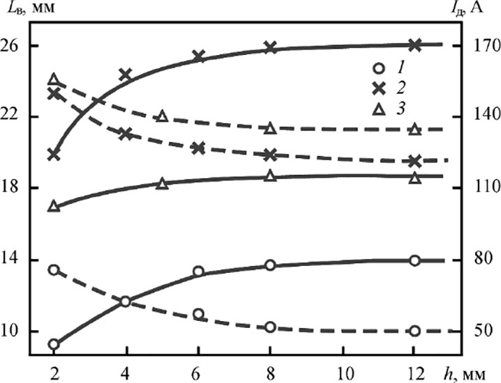
Figure 7. Dependence of weld pool length Lp (solid) and arc current Ia (dashed) on flight height h at tip width b: 1 — b = 4; 2 — 7; 3 — 15 mm
The higher the flight, the more obvious pool elongation is. In real parts the flight height is usually changed from 2 to 3 mm (dosing zone) up to 15–20 mm (filling zone). Under these conditions the length of weld pool at similar surfacing rate in one place of the screw can be less critical, and in the other, vice versa, more critical.
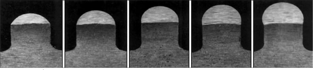
In addition to length of a weld pool selection of the optimum parameters of surfacing mode requires also considering the shape of bead cross-section, which determines machining allowances. It to larger extent depends on surfacing rate and PTA torch zenith displacement. Effect of these parameters on bead shape with similar area of cross-section is shown on macrosections (Figure 8).
 (zenith displacement 11 mm) and different displacement from zenith (b) (surfacing rate 8 m/h)")
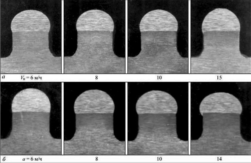
Figure 8. Macrosections of beads of similar section deposited on tips of flights of 7 mm width with different rates (a) (zenith displacement 11 mm) and different displacement from zenith (b) (surfacing rate 8 m/h)
(Open image in full size: )
As can be seen (Figure 8, a) rise of Vs at constant displacement of PTA torch from zenith a deteriorates the bead shapes. They became more convex and provoke decrease of side overhanging of the deposited metal. It takes place due to elongation of tail part of the weld pool since rise of Vs obligatory requires increase of welding current.

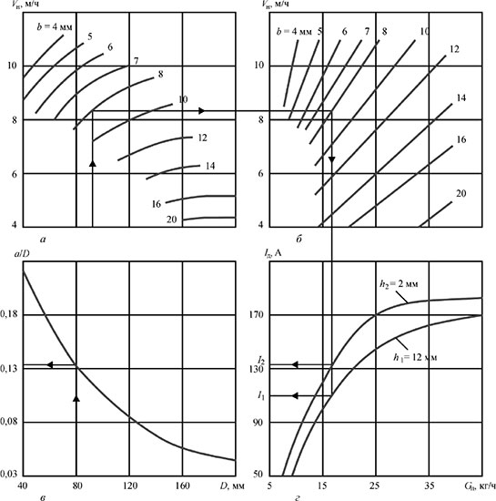
Figure 9. Nomograms for selection of parameters of screw surfacing mode: a — surfacing rate Vs; b — powder feed Gf; c — PTA torch displacement from zenith a; d — arc current Ia
(Open image in full size: )
Increase of PTA torch zenith displacement to the side opposite to part rotation vice versa improves the bead shape (Figure 8, b). They became wider and flatter since they are formed under conditions of higher arc pressure. However, the displacement can be increased only to some extent, which does not violate the equilibrium between hydrostatic pressure of liquid metal of weld pool and arc pressure. Based on our data the displacement should not exceed 2/3Lb. In practice, it is approximately (0.10–0.12)D. In the other case it will be difficult to hold the pool on the flight surface and liquid metal start dripping. This parameter is particularly important in surfacing of the small diameter parts of 40–60 mm. Zenith displacement can be increased to 0.2D at rise of part diameter and width of flight, when surfacing is carried out with PTA torch oscillations. Thus, effect on the surfacing process of arc current, surfacing rate and PTA torch zenith displacement, the three parameters which are tightly connected with each other, becomes apparent through change of size and shape of the weld pool.
Carried investigations show that there is comparatively narrow area of surfacing modes for each dimension type of the part, which provides favorable bead shape and absence of liquid metal dripping. The results of investigations of effect of surfacing technological parameters on bead formation were processed using a mathematical statistics method. The calculation considers not only the modes of surfacing, which provided the optimum section of deposited bead, its good formation and minimum penetration of the base metal. Number of points for observation made 78. Obtained data were used for plotting nomograms for selection of surfacing modes convenient for practical application (Figure 9).
For example, they show a sequence of selection of a mode for surfacing of 90 mm diameter screw with flight tip width 8 mm. The surfacing parameters, namely powder feed and PTA torch zenith displacement are constant along the whole screw length, and arc current at transfer from filling zone to dosing zone shall increase from I1 to I2 in accordance with decrease of flight height h1 to h2.
As it was already mentioned, at flight width more than 8 mm the surfacing is carried out with PTA torch oscillations. In this case amplitude A and oscillation frequency f are determined on formulae:

The proposed procedure allows orienting in the selection of the optimum parameters of surfacing mode, which in practice shall be specified depending on thermophysical properties of base and filler materials, fraction of powder and PTA torch design.
Equipment for surfacing. Plasma-Master Ltd. Company has developed two types of equipment for PTA surfacing of screws of extruders and automatic molding machines. These are installations developed based on turning lathes having own bed with rotator and rear center.

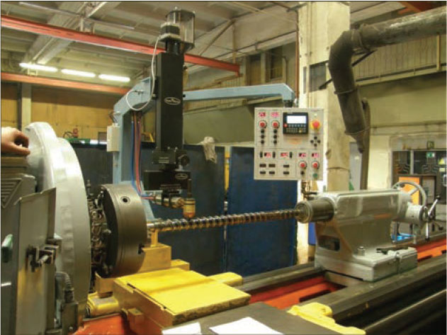
In the first case the lathe is used as a ready-made bed, on support of which specially developed surfacing apparatus PM-300 is installed. It contains PTA torch, oscillation mechanism with corrector, power feeder, lifting mechanism and control panel. The dimensions of lathe are selected depending on the maximum length of deposited parts. Kinematics of the lathe after small transformations allows rotating the part with necessary rate and moving the apparatus with PTA torch with set surfacing step. The process of surfacing is regulated from one panel located on the apparatus.
The control system is made on the basis of PLC, which allows accurately adjust to a pitch of screw flights and follow the process parameters. The installation also includes a control cabinet, inverter welding power source and autonomous cooling unit of the PTA torch. Such type of installation is reasonable for development if the Customer has available turning lathe of necessary length. Regardless, some inconveniencies in work, such an approach allows significantly reducing total cost of the installation. Figure 10 shows an example of such installation.

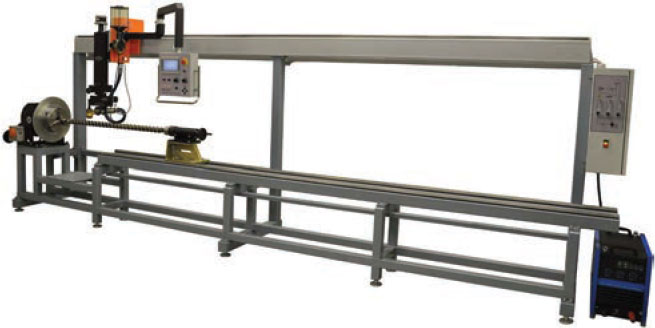
Figure 11. Installation RM-70 for PTA surfacing of screws of extruders and automatic molding machines
In other cases it is more reasonable to use special installation PM-307 (Figure 11). It initially contains all necessary mechanisms driven from general panel. Step motors are used as drivers. The guides, on which the surfacing apparatus is moved, are located on a beam in the top part of the installation that allows preventing falling on them of filler powder and, thus, their preliminary wear-out.
The installation uses a rotator with tilt axis, which permits surfacing of cylinder as well as conical edge surfaces. In becomes more versatile in such a variant. The installation can surface the cylinder parts of 20–300 mm diameter and 4500 mm length in automatic and semi-automatic modes. Number of steer axes can be from 3 to 5.
Consumables. Following the conditions of operation and design peculiarities of screws of extruders and automatic molding machines, the alloys designed for their surfacing shall satisfy a series of requirements. In addition to high wear-resistance, they shall have sufficient corrosion resistance at processing of aggressive polymers, good compatibility at friction with cylinder metal and high technological properties in surfacing. Nickel and cobalt based alloys are the most often used in the world practice for these purposes. In order to eliminate cracks in the deposited layer the parts are preheated till 400–500 °C temperature and sometimes concurrent heating is used.
: a — optical microscope (×500);
b — electron microscope (×3000)")
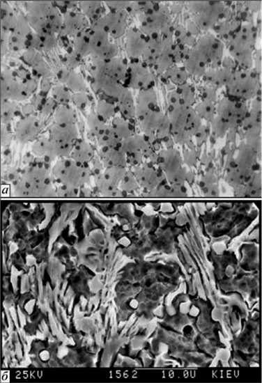
Figure 12. Microstructure of metal, deposited with powder PR-Kh18FNM (PMalloy21): a — optical microscope (×500); b — electron microscope (×3000)
(Open image in full size: )
The experience shows that preheating of such parts not only complicates the surfacing process, but significantly raises its price. Wear- and crack-resistant alloy based on iron of Fe–Cr–V–Mo–C system [9, 10], was developed especially for PTAS of screws with the participation of author. Today, it is produced in form of powder of PR-Kh18FNM grade (PMalloy21). This alloy refers to high-vanadium cast iron class. The peculiarity of structure of this alloy is very fine grain (10–15 mm) and fan-shaped form of eutectics, located as separate colonies like being implemented in austenite- martensite matrix (Figure 12).
Such eutectic structure provides alloy with combination of high strength and ductility s = 1000 MPa and as = 25∙102 MPa. Metal hardness after surfacing makes HRC 43–45. After tempering at 650 °C temperature for 2 h its hardness due to secondary hardening rises to HRC 52–53. The main wear-resistant phase of the alloy is vanadium carbides VC.

Conclusions
- Shape of bead at plasma surfacing on narrow tip of screw flight depends on fullness (cross-section area), deposition rate and PTA torch zenith displacement. To provide the best bead formation it is necessary that zenith displacement equals to approximately 2/3 of weld pool length, and length of the pool itself shall not exceed 0.22–0.26 of part diameter.
- The proposed procedure for selection of screw surfacing modes allows orienting on the selection of the main process parameters, namely arc current, deposition rate, powder feed and PTA torch zenith displacement depending on part geometry, i.e. diameter, width and height of flights.
- Developed equipment, technology and surfacing powder PR-Kh18FNM (PMalloy21) allow efficient repair of worn-out screws as well as significant rise of their wear resistance in comparison with new nitrated parts.
References
1. Luelsdorf, P. (1975) Verschleissprobleme mit Zylinder und Schnecke beim Extrudieren. Reilloy-Bericht, 4, 1–8 [in German].
2. (1977) Plasma arc weld surfacing – new route to hardfacing screws. Plastics Technology, 23(10), 17–19.
3. Frumin, I.I., Som, A.I., Gladky, P.V. (1981) Plasma surfacing of screw extruders of polymer machines. In: Theoretical and technological principles of surfacing. Surfacing in machine-building and repair: Transact. Kiev, PWI, 13–21 [in Russian].
4. Som, A.I., Gladky, P.V., Pereplyotchikov, E.F. (1985) Increase of service life of extruders by plasma surfacing. In: Surfacing. Experience and efficiency of application. Kiev, PWI. 89–93 [in Russian].
5. Gorka, J., Czuprynski, A., Kik, T., Melcer, M. (2011) Przemyslowe aplikacje napawania plazmowego proszko-wego. Przeglad Spawalnictwa, 9, 87–94 [in Polish].
6. Som, A.I., Gladky, P.W. ( 1984) Peculiarities of plasma surfacing on narrow substrate. In: New processes of surfacing, properties of deposited metal and transition zone. Kiev, PWI, 20–24 [in Russian].
7. Emelyanov, I.A. (1972) Influence of forces of surface tension and external pressure on shape of deposited bead surface. In: Transact. of LIVT Tekhnologiya Sudostroeniya i Remonta, 135, 135–145 [in Russian].
8. Yakobashvili, S.B. (1974) Influence of forces of surface tension and external pressure on shape of deposited bead surface. Welding processes in metallurgy. Tbilisi, Metsniereba, 1, 89–99 [in Russian].
9. Som, A.I., Gladky, P.V., Pereplyotchikov, E.F. (1983) New wear-resistant alloy for plasma surfacing. In: Theoretical and technological principles of surfacing. Surfacing consumables. Kiev, PWI, 7–11 [in Russian].
10. Som, A.I. (2016) Iron-based alloy for PTA surfacing of screw conveyors of extruders and injection molding machines. The Paton Welding J., 7, 21–25.
11. Gladky, P.V., Pereplyotchikov, E.F., Ryabtsev, I.A. (2007) Plasma surfacing. Kiev, Ekotekhnologiya [in Russian].