Effect of scheme of powder feeding into arc on its losses and efficiency of plasma-powder surfacing process
A.I. SOM
" The Paton Welding Journal". - 2015. - №5-6. - pp. 22-25.
Area of investigation was powder losses in plasma-powder surfacing using plasmatrons with internal and external schemes of its feeding into arc. Dependence of powder losses on its fraction, geometry of deposited bead and surfacing efficiency was shown. It is determined that losses of powder from steel 10Kh18N10T are 4—5 times lower at internal scheme of feeding, due to its more effective heating in the arc than at external one and do not exceed 1—2 % under favorable conditions. Practical recommendations on efficient application of plasmatrons with different systems of powder feeding are given. 4 Ref., 1 Table, 6 Figures.
Keywords: plasma-powder surfacing, powder losses, plasmatron, scheme of powder feeding, heating efficiency, particle flying path, bead formation
Efficiency of process of plasma-powder surfacing (PPS) mainly depends on heating efficiency and melting of filler powder in arc. The better powder heating in the arc is, the less its losses and the higher surfacing productivity are under the same process parameters. Besides, base metal penetration is lower and formation of deposited bead is better.
It is well-known fact [1] that efficiency of powder heating in PPS depends to significant extent on scheme and parameters of its feeding in arc. They determine flaying path and velocity of particles as well as time of their staying in the arc. Details on process of powder heating and melting in the arc are given in works [2, 3]. Practical recommendations of these investigations made a basis for development of current plasmatrons [4].
 and external (b) scheme of powder feeding in arc: 1 – electrode; 2—4 – plasma-shaping, protective
and focusing nozzle, respectively; 5 – part")

Figure 1. Internal (a) and external (b) scheme of powder feeding in arc: 1 – electrode; 2—4 – plasma-shaping, protective and focusing nozzle, respectively; 5 – part
Today internal and external schemes of powder feeding in arc [3, 4] are the most widely used for PPS. In the first case (Figure 1, a), powder is fed in the arc inside the plasmatron in form of uniformly distributed on circumference flow of particles through cone slot formed by plasma and focusing nozzles. In the second one (Figure 1, b), it takes place outside the plasmatron through one or several holes at the end of plasma-shaping nozzle. Focusing nozzle is absent in this case.
Aim of the present work is providing quantitative evaluation to these schemes from point of view of powder losses, efficiency and safety of surfacing process and, based on mentioned above, make a proposal on practical recommendations of their reasonable application.
Powder losses were investigated in surfacing of beads of various width and thickness with different efficiency over flat samples from steel 20. Bead width was varied in 5—30 mm range,variation of thickness made 1—5 mm and efficiency 10—50 g/min. Stainless steel powder of 10Kh18N10T type (analog AISI 321) of two fractions 63—100 and 100—200 μm were used as filler material. As indicated in work [3], the dependencies of movement and heating of this type of powder in the arc are typical for majority of powders used for PPS. Besides, it is relatively refractory and has short pool in surfacing that is very important in powder loss investigation.
The investigations were carried out on Plasma- Master Ltd. equipment using PP-6-01 plasmatron [4], which has internal system of powder feeding, and experimental plasmatron with external powder feeding system, similar to applied in plasmatrons of leading world manufacturers Castolin, Deloro Stellite, Commersald etc.
 and experimental plasmatron (b)")
Powder in PP-6-01 plasmatron firstly enters a special distribution chamber through inlet connection, where it is uniformly distributed around the circumference, and then being fed in the arc via a system of slots, evenly located on conical surface of plasma-shaping nozzle. The slots guide the powder particles directly in the central most heated part of the arc. Focus point of powder particles is at 3 mm distance from the end of focusing nozzle. Diameters of plasma-shaping and focusing nozzles in these experiments equaled 5 and 8 mm, respectively.
Filler powder in the experimental plasmatron is preliminary divided on two similar flows and being fed in the arc directly through two holes of 1.4 mm diameter made in diametric opposition to each other at the end of plasma-shaping nozzle. Angel of powder feeding in arc relatively to vertical axis makes 35°, the same as in PP-6-01 plasmatron. Focus point of powder particles is at 8 mm distance from the end of plasma-shaping nozzle, diameter of which equaled 5 mm in experiments. Plasmatron in surfacing was oriented in such a way that powder feeding takes place in plane normal to axis of deposited bead. In both cases plasmatron distance to surface being deposited was 10 mm.
 and internal (2) schemes of its feeding
in arc: a – 63—100 μm powder fraction; b – 100—200 μm")

Figure 3. Dependence of powder loss on width of deposited bead at external (1) and internal (2) schemes of its feeding in arc: a – 63—100 μm powder fraction; b – 100—200 μm
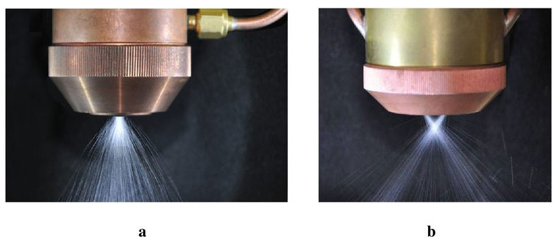
Figure 2 shows plumes of powder flowing from PP-6-01 plasmatron (Figure 2, a) and experimental plasmatron (Figure 2, b) at 50 g/min feeding. Consumption of transporting gas in both cases was minimum for elimination of powder blockage in the channels of plasmatrons and made 2 l/min. At that, initial velocity of particle flight at the moment of their entrance in the arc equaled 1.0—1.5 m/s for PP-6-01 plasmatron and 2— 3 m/s for experimental one. Such variations are caused by different resistance of channels for powder feeding in these systems.
Powder loss was determined as difference between general consumption of powder supplied by feeder and mass of metal deposited for the same time. Mass of deposited metal was determined by means of weighting of the sample before and after surfacing. Surfacing distance made 200 mm. Weighing of the samples was carried out using laboratory scales of up to 0.05 g accuracy.
 and internal (2) schemes of its feeding
in arc: a – 63—100 μm powder fraction; b – 100—200 μm")

Figure 4. Dependence of powder losses on height of deposited bead at external (1) and internal (2) schemes of its feeding in arc: a – 63—100 μm powder fraction; b – 100—200 μm
Experiments showed that the largest powder losses were observed with external scheme of its feeding in the arc. Particularly, it becomes apparent in deposition of narrow and thin beads using coarse-grain powder. They achieve 20 % (Figures 3, b and 4, b) in such cases. Increase of width and thickness of the beads provides for significant reduction of powder loss due to more favorable conditions for powder entering into the weld pool. Using of finer powder promotes more significant decrease of losses, however, they are still large enough and make 8—10 % (Figures 3, a and 4, a).
Such significant powder losses at external feeding scheme are firts of all caused by unfavorable conditions of its heating in the arc. Time of powder staying and heating in the arc is limited due to low position of point for powder feeding and large initial particle velocity. Moreover, local jets of cold transporting gas deform arc column and reduce plasma temperature in heating zone. Calculation data of work [3] show that only particles finer than 50 μm can be heated to melting temperature of 10Kh18N10T steel at such feeding scheme. Larger particles, which did not come into weld pool, flew past and got lost.
")

Figure 5. Dependence of powder losses on value of feeding at different schemes of its feeding in arc: 1 – external; 2 – internal (63—200 μm powder fraction, bead width of 20 mm, height of 3 mm)
Significantly better results are observed at internal powder feeding. Regardless the fact that dependencies are in general close, the level of powder losses here is considerably lower. Also, the difference between fine and coarse fractions is not large. Under the most unfavorable conditions powder losses do not exceed 5 % versus 20 % at external feeding. Powder losses make only 1—2 % (see Figures 3, a and 4, a) in surfacing of wide and full beads.
It was noted during the experiment that powder losses depend not only on geometry of deposited bead, but on productivity of process performance as well. Increase of powder feeding promotes for also increase of loss, in particular, at external feeding (Figure 5).
 and external (b) schemes of powder feeding in arc")
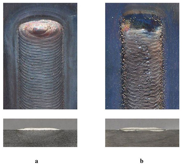
Figure 6. View and macrosections of beads at internal (a) and external (b) schemes of powder feeding in arc
(Open image in full size: )
It can be explained by the fact that increase of powder feeding provides for rise of particle density in the arc and possibility of their elastic collision between themselves at the moment of entering in the arc is increased, as a result of which they fly off from the arc and get lost. Probability of particle collision is significantly more at external feeding due to the fact that powder is fed in the arc by more concentrated flows towards each other. The important indices of surfacing efficiency in addition to powder loss are also formation of layer, penetration of base metal and specific consumption of energy. Here, internal scheme of powder feeding also has obvious advantages, in particular at fine layer surfacing.
Figure 6 shows view and macrosections of cross section of 20 mm width and 1 mm height deposited beads. It can be seen that formation of bead deposited at internal powder feeding is significantly better, and base metal penetration is obviously lower than at external one. It is achieved due to better heating of powder in the arc and larger factor of its use. In this case, energy distribution of plasma arc is so that its larger part is consumed for powder heating, not for part, i.e. heat input in the part is significantly lower. Flow of transporting gas uniformly distributed around the circumference provides for additional stabilizing effect on arc and also promotes improvement of bead formation. The result of common effect of these factors shows that surfacing with internal powder feeding is more energetically profitable than at external one. Surfacing current necessary in this case is 10—15 % lower at the same efficiency.
The Table shows for example the optimum values of arc current in surfacing of different geometry beads using both schemes of powder feeding in arc.
Optimum values of current at deposition of different geometry beads
| Geometry of beads, mm | Surfacing speed, mm/min | Powder feeding rate, g/min | Powder fraction, μm | Surfacing current, A | |
| Internal feeding | External feeding | ||||
| b = 10 h = 3 | 140 | 26 | 63—100 | 170 | 190 |
| 100—200 | 180 | 205 | |||
| b = 20 h = 3 | 70 | 34 | 63—100 | 175 | 200 |
| 100—200 | 180 | 210 | |||
| b = 30 h = 3 | 50 | 38 | 63—100 | 180 | 220 |
| 100—200 | 190 | 230 | |||
Carried investigations showed that internal scheme of powder feeding provides for significantly better indices of surfacing than external one. However, appearance of drops of liquid metal at the output of focusing nozzle was observed at long-term surfacing of powder fraction of less than 100 μm with large productivity. It resulted in deterioration of process stability and degradation of deposited bead formation. Reduction of productivity and, respectively, surfacing current significantly decreases droplets appearance. They were completely absent at less than 150 A current. No droplets were also observed in use of coarse fraction powder of more than 100 μm at current up to 300 A. External scheme of powder feeding in arc did not show such an effect in all investigated range of currents (50—300 A). It should be taken into account in practice, particularly, in surfacing of fusible self-fluxing nickelbased powders.
Conclusions
- Powder losses are significantly less at internal scheme of its feeding in arc than at external one, and under favorable conditions do not exceed 2 %.
- Internal scheme of powder feeding in the arc in general more efficient in comparison with external one. It provides for smaller powder losses, lower penetration of base metal and better formation of deposited bead at decreased energy consumption.
- Increase of surfacing efficiency using of plasmatrons with external powder feeding requires application of powders with finer fraction of less than 100 μm, and more than 100 μm for plasmatrons with internal feeding.
- In order to reduce losses of powder in surfacing by plasmatron with external powder feeding the process should be carried at small productivity of less than 30 g/min.
References
- 1. Gladky, P.V., Pavlenko, A.V., Zelnichenko, A.T. (1989) Mathematical modeling of powder heating in arc during plasma surfacing. Avtomatich. Svarka, 11, 17—21, 54.
- Pavlenko, A.V., Gladky, P.V. (1989) Peculiarities of filler powder heating in arc during surfacing. Ibid., 11, 33—37.
- Gladky, P.V., Pereplyotchikov, E.F., Ryabtsev, I.A. (2007) Plasma surfacing. Kiev: Ekotekhnologiya.
- Som, A.I. (1999) New plasmatrons for plasma-powder surfacing. Avtomatich. Svarka, 7, 44—48./li>