Iron-based alloy for plasma-powder surfacing of screw conveyors of extruders and injection molding machines
A.I. SOM
"THE PATON WELDING JOURNAL". - 2016.
- №7. - pp. 21-25.
The structure and properties of wear- and corrosion-resistant alloy of Fe–Cr–V–Mo–Ni–C system were investigated
for plasma surfacing of screw conveyors of extruders and injection molding machines. It was shown that combination
of high wear resistance and ductility of the alloy is achieved due to formation of a large amount of primary vanadium
carbides VC and eutectics, located in the viscous austenitic-martensitic matrix in the form of single colonies. The alloy
has an excellent formation and high resistance of the deposited bead to crack formation in surfacing, that allows surfacing
rather massive parts without preheating. The service life of screw conveyors deposited using this alloy is 3–5 times
higher than that of nitrated screws. 10 Ref., 2 Tables, 10 Figures.
Keywords: plasma-powder surfacing, alloy structure, carbides, carbide eutectic, wear resistance, coefficient of
linear expansion, bead formation
To increase the service life of screw conveyors of
extruders and injection molding machines the plasma-
powder surfacing of working surfaces using
wear-resistant alloys is widely applied in the world
[1–5]. Most often for these purposes the alloys are
used based on nickel and cobalt. To avoid cracks in
the deposited layer the parts are preheated to 400–
500 °C, and sometimes the concurrent heating is used.
The experience shows that preheating of such
parts not only complicates the process of surfacing,
but also significantly raises its cost. In addition, the
widespread use of nickel and cobalt alloys for surfacing
of screw conveyors is rather traditional than
it is caused by the necessity. Although such unique
properties as heat resistance, hot hardness, corrosion
resistance and others are important in the operation
conditions of screw extruders, however they are not
decisive. Therefore, according to the author opinion,
they can be successfully replaced for the cheaper and
more wear-resistant alloys based on iron.
Unfortunately, the known commercial alloys based
on iron have the same serious technological disadvantage
as nickel or cobalt alloys, namely increased tendency
to crack formation during surfacing. There is an
experience of application of high-speed steel 10R6M5
for the surfacing of screw conveyors, which under the
certain thermal cycle due to the effect of martensite
transformation can be deposited without cracking [6].
However, as was demonstrated by industrial tests, due
to insufficient ductility of this steel during operation
the cracks may be formed in the deposited layer and
cause cleavages, that is unacceptable.
Specially for plasma-powder surfacing of screw
conveyors, the author of this article together with
other authors developed a new wear-resistant alloy of
system Fe–Cr–V–Mo–C resistant to cracks [7]. It belongs
to the class of high-vanadium cast irons. During
its development the maximum operating conditions of
these components and their structural features were
taken into account.
In the present work for the first time the properties
of the alloy for surfacing of screw conveyors, and experience
of its industrial operation are described in detail.
Structure and phase composition of the alloy
after surfacing. The microstructure and phase composition
of the deposited metal was investigated by
optical and electron metallography, as well as using
the methods of X-ray diffraction, X-ray spectral and
chemical phase microanalyses (the investigations
were carried out at PWI).
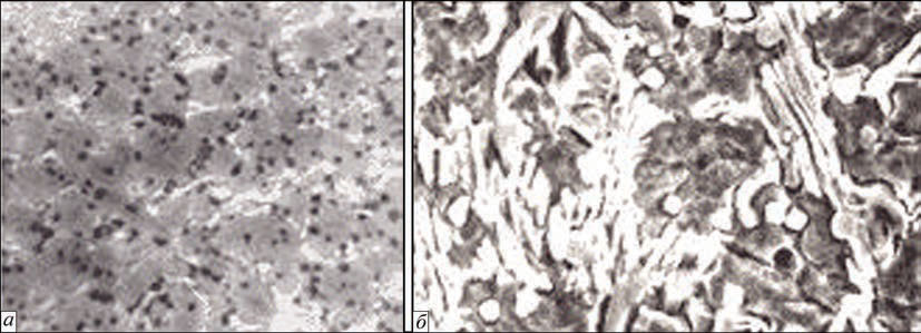
Figure 1. Microstructure of deposited metal: a — optic microscope (×500); b — electron microscope (×3000)
Figure 1. Microstructure of deposited metal: a — optic microscope (×500); b — electron microscope (×3000)
The structure of metal in the initial state after surfacing
consists of a solid solution, based on iron, carbide
eutectic and excessive vanadium carbides VC.
The characteristic feature of the structure is a very
fine grain (10–15 mm) and eutectic of a fan shape,
which are located in the form of separate colonies as if
embedded into the matrix (Figure 1, a). The shape and
structure of eutectic colonies are clearly visible in the
SEM-photo (Figure 1, b), produced by microscope
JSM-35, where thin plates of eutectic carbides are alternated
with a solid solution filling the gaps between
them. Such a structure of eutectic provides the alloy
with a combination of high strength and ductility at
the level of σt = 1000 MPa and σstyle=n = 25 kg/cm2.
The vanadium carbides are fine (up to 5 mm), have
a rounded shape, and are comparatively uniformly
distributed throughout the whole volume of the alloy.
The total amount of carbide phase, according to thedata of chemical phase analysis, is about 16 %. As was shown by X-ray structural analysis of anode precipitation,
except of vanadium carbides, the composition
of carbide phase VC includes eutectic carbides,
based on chromium of Me7C3 type, molybdenum of
Me2C type and carbides of cementite type Me3C,
where a part of iron atoms is replaced by atoms of
other elements. The matrix of the alloy represents (γ +
α)-solid solution with microhardness HV25-400–450.
According to the data of X-ray microanalysis, the solid
solution contains about, %: 15Cr, 3V, 2Mo, 5Ni.
A high degree of alloying of the solid solution with
the given elements significantly delays γ → α transformations.
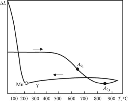
As is shown by investigations performed
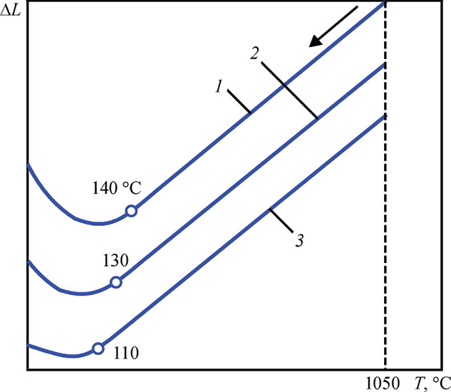
at a high-speed dilatometer under the continuous
cooling from high temperatures (Figure 2), the starting
point of martensitic transformation Ms, depending
on the cooling rate, lies at the level of 110–130 °C.
Figure 2. Dilatometric curves at continuous cooling of deposited
metal from high temperatures
Figure 2. Dilatometric curves at continuous cooling of deposited
metal from high temperatures (Open image in full size: )
Due to this fact, up to 60–80 % of residual austenite
is fixed in the alloy. It causes a beneficial effect to
the ductility of the alloy and allows relaxing a significant
part of stresses arising during rapid cooling at
surfacing process.
Structure and phase composition of the alloy
after heat treatment. In manufacture of screw conveyors
the obligatory technological operation is high
tempering, therefore, it is important to know its effect
on the structure and properties of the deposited
metal. The investigations carried out in the vacuum
differential Chevenar dilatometer, provide insight on
the structural sensitivity of the alloy to the subsequent
heating and cooling.
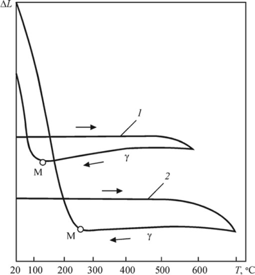
Figure 3. Dilatometric curve at continuous heating and cooling of deposited metal at 150–170 °C
Figure 3. Dilatometric curve at continuous heating and cooling of deposited metal at 150–170 °C
As is seen from the dilatometric curve (Figure 3)
the phase γ ↔ a transformation occur in the deposited
metal. The critical points are expressed quite clearly:
Ac1 lies at the level of 650 °C, Ac3 is at 850 °C.
During cooling the martensitic transformation
with a significant volume effect occurs. It should be
noted that structural transformations in the metal,
characterized by reduction in volume (the curve is
bent downwards), begin a little earlier, approximately
at 550 °C. At these temperatures the precipitation of
fine-dispersed chromium, molybdenum and vanadium
carbides from supersaturated austenite begins.
The abovementioned is confirmed by dilatograms
of tempering at these temperatures (Figure 4), indicating
a significant volume effect of additional martensite
transformation, which occurs in the alloy due to
depletion of austenite with the alloying elements and
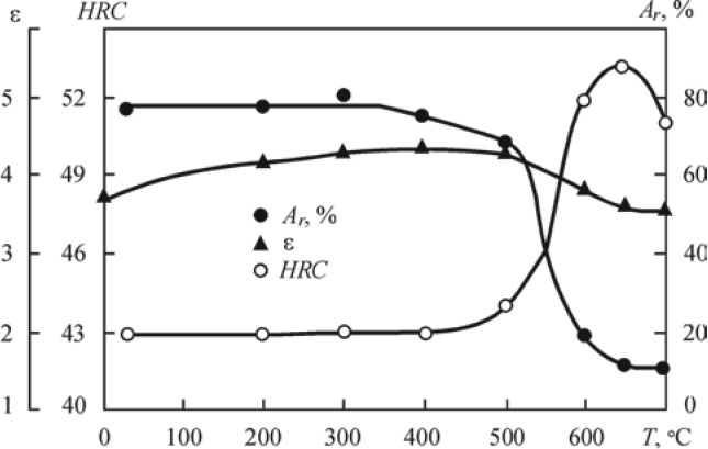
reduction of its resistance to decay. The HRC hardness
of the deposited metal at the same time increases
from 43–44 to 52–53 (Figure 5). Its maximum value
is achieved at the tempering temperature of 650 °C.
Also at the same temperature the maximum decay of
austenite is observed. The increase in duration of exposure does not cause a noticeable increment in hardness
since the most intensive precipitation of carbides
is apparently occurs at the initial period.
Figure 4. Dilatometric curves of tempering of deposited metal: 1 — 600 °С, 1 h; 2 — 700 °С, 1 h
Figure 4. Dilatometric curves of tempering of deposited metal: 1 — 600 °С, 1 h; 2 — 700 °С, 1 h
After tempering at 700 °C, due to a greater depletion
of austenite, the volume effect of martensite
transformation is expressed more clearly (see Figure
4, curve 2), although the hardness of deposited
metal the is somewhat lower (see Figure 5). Here the
reduction in hardness, as compared to tempering at
650 °C, occurs apparently due to decomposition of
the initial martensite and carbides coagulation
Figure 5. Influence of tempering temperature on hardness HRC, wear resistance e and amount of residual austenite Ar
Figure 5. Influence of tempering temperature on hardness HRC, wear resistance e and amount of residual austenite Ar
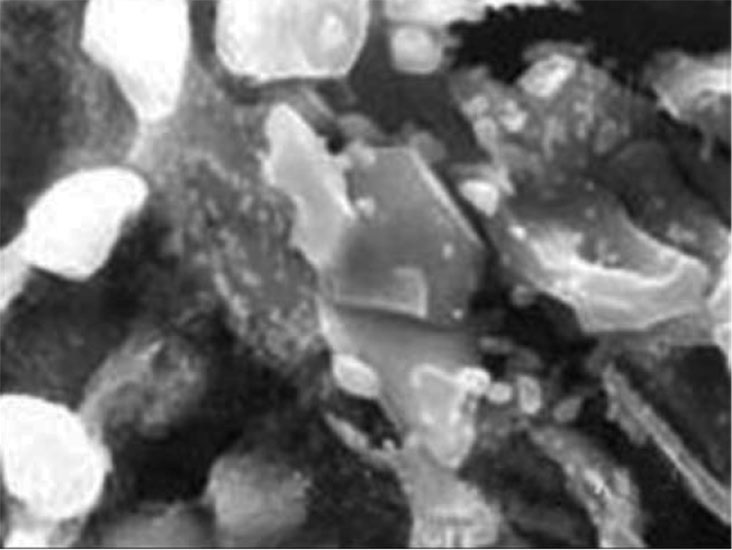
The precipitation of dispersed carbides at tempering
of the alloy was managed to be revealed by SEM
investigations. In Figure 6 the typical places of precipitation
of these carbides are shown. They are originated
both in the grains of solid solution, as well as in
eutectic colonies, apparently in those places where the
most favorable thermodynamic conditions for their
formation exist, like dislocations in martensite, phase
boundaries, etc.
Figure 6. Precipitation of thin-dispersed carbides in the alloy after
tempering at 650 oC for 1 h
Figure 6. Precipitation of thin-dispersed carbides in the alloy after
tempering at 650 oC for 1 h
Service properties of deposited metal. Taking into
account structural sensitivity of deposited metal to heat
treatment, let us consider the influence of tempering on
its wear resistance and mechanical properties.
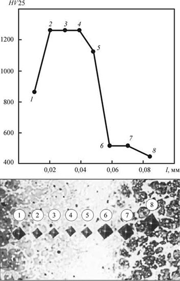
Figure 7. Distribution of hardness in nitrated layer of deposited metal
Wear resistance. The tests were carried out in laboratory
installation NK-M [8]. A fine-dispersed quartz
sand with grain size of ≤80 mm served as abrasive. As
a reference the specimens of annealed steel 45 were
used.
As is seen from Figure 5, at first the wear resistance
of deposited metal grows to 400 °C in the range of
tempering temperatures and then slightly decreases. It
is connected, first of all, with the influence of tempering
on the amount and stability of residual austenite in
the alloy, which plays a large role in wear processes
[9, 10]. The positive role of metastable austenite consists
in the fact that not only properly itself is a good
resistant to abrasive wear, but also firmly preserves
the fine vanadium carbides against spalling during
friction due to formation of martensite deformation
in the surface layer. After low and medium tempering
the total amount of residual austenite is still retained,
but as a result of diffusion redistribution of carbon its
stability decreases and more favorable conditions for
formation of deformation martensite are created, by
which the observed increase in wear resistance may
be explained.
High tempering, especially at 650 oC, causing decay
of residual austenite, causes a somewhat reduction
of wear resistance of the alloy as compared to
medium tempering, though the hardness in this case
is much higher.
The additional wear resistance of the deposited
metal is given by nitration, which, as a rule, is applied
to protect the rest part of the screw conveyor from
wear in manufacture of new parts. Due to high alloying
of the metal, a nitrated layer is produced not deep
(up to 0.05 mm), but very hard (HV25-1288 (Figure
7)). Due to this, the wear process of the deposited
metal, especially at the initial stage, is significantly
delayed.
Table 1. Chemical composition and hardness of alloys tested
Content of elements, wt.%
Hardness
HRC
С
Si
Mn
B
Cr
V
W
Mo
Ni
Co
Fe
PG-SR4 (Kh15N75S4R4)
0.7
3.9
–
3.2
15.8
–
–
–
Res.
–
≤3
58
PG-10K-02 (Stellite 6)
1.1
2.1
–
–
28.1
–
4.4
–
–
Res.
–
42
PG-S1 (Sormite 1)
2.7
2.9
2.7
–
28.6
–
–
–
4.3
–
Res.
46
PR-Kh18FNM (PMalloy 21)
2.2
0.8
0.9
–
18.2
7.2
–
2.2
2.6
–
Res.
43
Figure 8 shows the results of comparative tests in
the same conditions of the considered alloy and some
typical representatives of wear-resistant Ni-, Co-, Fe- based alloys. The chemical composition of the tested
alloys is given in Table 1.
As is seen from Figure 8, the relative wear resistance
of the new alloy both in the initial state as well
as after tempering with nitration is considerably higher
than that of nickel (PG-SR4) and cobalt (Stellite 6)
alloys. After nitration, it also becomes higher than that
of alloy Sormite 1.
Figure 8. Relative wear resistance of tested commercial alloys
Coefficient of linear expansion. CLE is an important
characteristic for evaluation of operability of
deposited product under the conditions of elevated
temperatures. The closer are the CLE values of the
deposited and base metals, the lower the level of residual
stresses, the lower deformation of the deposited
part and, finally, the better operating conditions of
bimetallic part.
The results of measuring the CLE of the considered
alloy at different temperatures are given in Table
2. For comparison, the data for steel 40KhN used
as the base metal for manufacture of the screw conveyors
were also given.
CLE in the temperature range from 20 °C to
100
200
300
400
500
600
700
Alloy PR-Kh18FNM (PMalloy21)
After surfacing
13.3
13.6
14.0
14.1
14.7
15.0
–
After tempering (600 °C, 1 h)
10.5
10.7
10.8
11.0
11.5
11.8
11.2
Steel 40KhN
Initial
11.8
12.3
–
13.4
–
14.0
–
As can be seen from the Table, CLE of the alloy
in as-surfaced state and after heat treatment are significantly
different, which is connected with a large
difference in the amount of residual austenite. Before
heat treatment, it is significantly higher. After tempering
at 600 °C, due to the decay of residual austenite,
the CLE becomes lower than that of steel 40KhN.
During heat treatment of deposited parts it should result
in redistribution of residual stresses with the formation
of compressive stresses in the deposited layer,
which, as is known, favorably affects the operability
of parts. From this point of view a high tempering is
useful.
During restoration of worn-out parts a high tempering
may result in unacceptable deformations
caused both by difference in CLEs of the deposited
and base metals, as well as volume effect of transformations
occurring in the deposited metal during tempering.
Therefore, in the given case, a medium tempering
should be applied at the temperature of 400 °C,
at which structural transformations in the deposited
metal are absent.
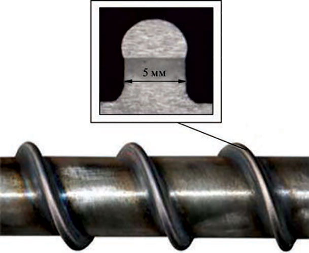
Figure 9. Appearance and macrosection of coil of deposited
screw conveyor of 63 mm diameter
Figure 9. Appearance and macrosection of coil of deposited
screw conveyor of 63 mm diameter
Experience of industrial application of the alloy.
The alloy developed as a powder is used in industry
for surfacing screw conveyors by the company «Plasma-
Master Ltd» predominantly in Ukraine. For more
than 20-year period a wide experience was gained on
surfacing and service of deposited parts both in processing
of simple as well as filled polymers. At the present
time the alloy is produced under trademark PMalloy 21.
In practice, the screw conveyors of casting and extrusion
equipment of diameter from 32 to 250 mm and
length from 600 to 5000 mm are surfaced. Powder
PMalloy 21 provides a good formation of deposited
metal (Figure 9) and a complete absence of cracks in
it, even on very massive parts, at a correct selection of
surfacing modes. This important technological advantage of the given alloy allows refusing from pre-heating
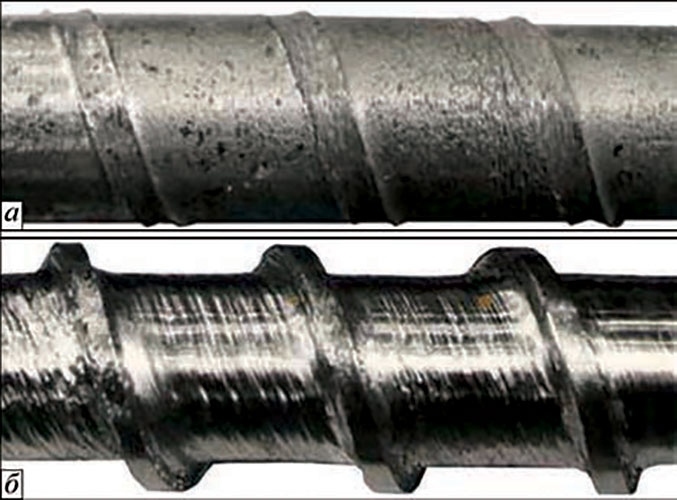
Figure 10. Appearance of screw conveyors of 45 mm diameter
after service during processing of polyamide: a — nitrated screw
without surfacing; b — screw deposited using alloy PMalloy 21
with subsequent nitration
Figure 10. Appearance of screw conveyors of 45 mm diameter
after service during processing of polyamide: a — nitrated screw
without surfacing; b — screw deposited using alloy PMalloy 21
with subsequent nitration
of the workpiece and, thus, significant simplifying
and cheapening the process of surfacing. The powder
can be successfully applied both in manufacture
of new screws as well as in restoration of worn-out
parts. In the latter case, due to a good formation of
deposited metal the machining is reduced only to the
finish grinding of coil comb in the diameter.
As compared to the nitrated screws the resistance
of the deposited ones grew in 3–5 times depending
on the type of the processed materials. In Figure 10
the appearance of two screw conveyors of injection
molding machine «Kuasy» is shown after service under
the same conditions during processing of filled
polyamide 6.6.
The photos convincingly prove the advantage of
screws, deposited using alloy PMalloy 21. In the first
case, the wear of coils is so great that almost nothing
left from them, and in the second case they were preserved
completely. Despite of some wear of the side
surfaces of coils and dents, the screw remains suitable
for the further operation and is able to provide a rated
efficiency of processing polymers.
At the present time alloy PMalloy 21 is successfully
used also for surfacing of other parts like blades of
mills for processing of secondary polymers, plungers
of hydraulic systems, axles, shafts, etc.
Conclusion
References
Conclusion
The complex investigations of structure and properties
of developed alloy PMalloy 21 and a long experience
of operation of deposited screw conveyors
convincingly show that the given alloy according to
its operability can successfully replace the Ni- and
Co-based alloys, traditionally used in industry for
surfacing these parts. It is more wear resistant, more
technological and considerably cheaper.
References
1. Maksimchuk, A.M., Mesyats, G.A., Nechiporenko, V.G. et al.
(1973) Manufacturing of new and plasma surfacing repair of
worn extruder worms. Khimich. i Neft. Mashinostroenie, 8,
22–23.
2. Luelsdorf, P. (1975) Verschleissprobleme mit Zylinder und
Schnecke beim Extrudieren. Reilloy-Bericht., 4, 1–8.
3. (1977) Plasma arc weld surfacing – new route to hardfacing
screws. Plastics Techn., 23(10), 17–19.
4. Gorka, J., Czuprynski, A., Kik, T. et al. (2011) Przemyslowe
aplikacje napawania plazmowego proszkowego. Przeglad Spawalnictwa,
9, 87–94.
5. Gladky, P.V., Pereplyotchikov, E.F., Ryabtsev, I.A. (2007)
Plasma surfacing. Kiev: Ekotekhnologiya.
6. Frumin, I.I., Som, A.I., Gladky, P.V. (1981) Plasma surfacing
of extruder worms of polymer machines. In: Theoretical
and technological principles of surfacing. Surfacing in machine-
building and repair: Transact., 13–21. Kiev: PWI.
7. Som, A.I. (1983) New wear-resistant alloy for plasma surfacing.
In: Theoretical and technological principles of surfacing.
Surfacing consumables: Transact., 7–11. Kiev: PWI.
8. Yuzvenko, Yu.A., Gavrish, V.A., Marienko, V.Yu. (1979) Laboratory
units for evaluation of wear resistance of deposited
metal. In: Theoretical and technological principles of surfacing.
Properties and tests of deposited metal: Transact., 23–27.
Kiev: PWI.
9. Poznyak, L.A., Skripchenko, Yu.M., Timaev, S.I. (1980) Die
steels. Moscow: Metallurgiya.
10. Popov, V.S., Titukh, Yu.I. (1975) X-ray structural examination
of transformations in work surface of alloys under abrasive
wear. MiTOM, 1, 24–27
; b — electron microscope (×3000)")